


21
Save These Instructions 3-90-775 Pellets or Corn/Pellet Mixture Only
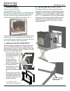
The control board is packaged in a static resistant
bag. Use care when handling, hold the circuit board
only by the edges. In a large replace opening, you
may have plenty of space for the circuit board to re-
main attached. For a smaller replace opening, you'll
likely need to remove the wiring from the circuit board
to route it through the side of the mounting frame and
out through the control opening. Follow these steps;
• Disconnect the 11 pin harness plug.
• Disconnect the red twisted ESP wire.
• Feed the harness wires and the ESP wire through
the opening in the mounting frame and out
through the control opening in the surround panel.
• Holding the control board outside the opening in
the surround panel, re-attach the harness plug
and the ESP wire.
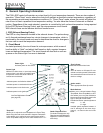
• After determining the location of the Room Sen-
sor (See next Section), Attach it to the two male
spade terminals near the top of the circuit board.
NOTE: These connections are not polarity specic.
• From the power cord, attach the green ground
wire to the grounding post located on the feeder
air intake snout.
• The black wire from the power cord gets attached
to the short brown wire from the control harness
• The white wire from the power cord will attach to
the short white wire on the control harness.
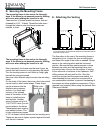
• Install the control panel into the surround; Right
side rst, then tilt in the left side.
• Secure using the four black machine screws in-
cluded with the surround.
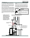
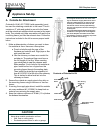
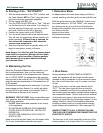
Although not required, it is recommended that the
room sensor be connected in every installation. Using
a minimum size 18 gauge wire, you may splice in an
additional length, to extend the room sensor. The fol-
lowing are typical locations for the room sensor;
• On an interior wall next to or in place of a typical
wall thermostat.
• On the leg of a coffee table or end table in your
favorite sitting location.
• Sticking out through the punched hole at the lower
right corner of the control panel.
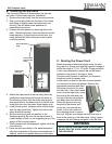
Once the location has been decided, run the wiring to
the control panel. You'll need to remove the two ter-
minals from the end of the sensor cable and replace
them with the two smaller terminals from the hardware
bag. Plug the terminals into the circuit board. These
connections are not polarity specic.
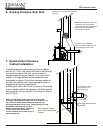
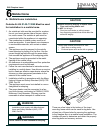
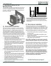
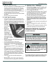
The rollers on the sides of the insert body will ride on
the rails of the mounting frame. Once the body is all
the way in, hook and close the top spring latches on
each side to secure.