


32
against insufficient airflow (combustion air and flue products)
through the heat exchanger and/or blocked condensate drain con-
ditions.
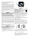
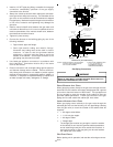
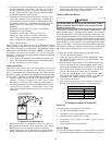
FLAME SENSOR
The flame sensor is a probe mounted to the burner/manifold as-
sembly which uses the principle of flame rectification to determine
the presence or absence of flame.
XVIII. TROUBLESHOOTING
ELECTROSTATIC D ISCHARGE (ESD) PRECAUTIONS
NOTE: Discharge body’s static electricity before touching unit. An
electrostatic discharge can adversely affect electrical components.
Use the following precautions during furnace installation and ser-
vicing to protect the integrated control module from damage. By
putting the furnace, the control, and the person at the same electro-
static potential, these steps will help avoid exposing the integrated
control module to electrostatic discharge. This procedure is appli-
cable to both installed and uninstalled (ungrounded) furnaces.
1. Disconnect all power to the furnace. Do not touch the
integrated control module or any wire connected to the control
prior to discharging your body’s electrostatic charge to
ground.
2. Firmly touch a clean, unpainted, metal surface of the
furnaces near the control. Any tools held in a person’s
hand during grounding will be discharged.
3. Service integrated control module or connecting wiring
following the discharge process in step 2. Use caution not
to recharge your body with static electricity; (i.e., do not move
or shuffle your feet, do not touch ungrounded objects, etc.).
If you come in contact with an ungrounded object, repeat
step 2 before touching control or wires.
4. Discharge your body to ground before removing a new
control from its container. Follow steps 1 through 3 if
installing the control on a furnace. Return any old or new
controls to their containers before touching any ungrounded
object.
DIAGNOSTIC C HART
HIGH VOLTAGE!
T
O
AVOID
PERSONAL
INJURY
OR
DEATH
DUE
TO
ELECTRICAL
SHOCK
,
DISCONNECT
ELECTRICAL
POWER
BEFORE
P
ERFORMAING
ANY
SERVICE
OR
MAINTENANCE
.
WARNING
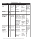
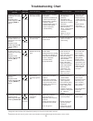
Refer to the Troubleshooting Chart at the end of this manual for
assistance in determining the source of unit operational problems.
The red diagnostic LED blinks to assist in troubleshooting the unit.
The number of blinks refers to a specific fault code.
RESETTING FROM L OCKOUT
Furnace lockout results when a furnace is unable to achieve igni-
tion after three attempts during a single call for heat. It is character-
ized by a non-functioning furnace and a one flash diagnostic LED
code. If the furnace is in “lockout”, it will (or can be) reset in any of
the following ways.
1. Automatic reset. The integrated control module will
automatically reset itself and attempt to resume normal
operations following a one hour lockout period.
2. Manual power interruption. Interrupt 115 volt power to the
furnace for 1 - 20 seconds.
3. Manual thermostat cycle. Lower the thermostat so that
there is no longer a call for heat then reset to previous setting.
Interrupt thermostat signal to the furnace for 1 - 20 seconds.
NOTE: If the condition which originally caused the lockout still
exists, the control will return to lockout. Refer to Section XVIII,
Troubleshooting - Diagnostic Chart for aid in determining the cause.
XIX. MAINTENANCE
HIGH VOLTAGE!
T
O
AVOID
PERSONAL
INJURY
OR
DEATH
DUE
TO
ELECTRICAL
SHOCK
,
DISCONNECT
ELECTRICAL
POWER
BEFORE
PERFORMING
ANY
MAINTENANCE
. I
F
YOU
MUST
HANDLE
THE
IGNITER
,
HANDLE
WITH
CARE
. T
OUCHING
THE
IGNITER
ELEMENT
WITH
BARE
FINGERS
,
ROUGH
HANDLING
OR
VIBRATION
COULD
DAMAGE
THE
IGNITER
RESULTING
IN
PREMATURE
FAILURE
. O
NLY
A
QUALIFIED
SERVICER
SHOULD
EVER
HANDLE
THE
IGNITER
.
WARNING
ANNUAL INSPECTION
The furnace should be inspected by a qualified installer, or service
agency at least once per year. This check should be performed at
the beginning of the heating season. This will ensure that all fur-
nace components are in proper working order and that the heating
system functions appropriately. Pay particular attention to the fol-
lowing items. Repair or service as necessary.
• Flue pipe system. Check for blockage and/or leakage. Check
the outside termination and the connections at and internal
to the furnace.
• Heat exchanger. Check for corrosion and/or buildup within
the heat exchanger passageways.
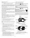
• Burners. Check for proper ignition, burner flame, and flame
sense.
• Drainage system. Check for blockage and/or leakage.
Check hose connections at and internal to furnace.
• Wiring. Check electrical connections for tightness and/or
corrosion. Check wires for damage.
• Filters.
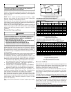
FILTERS
T
O
ENSURE
PROPER
UNIT
PERFORMANCE
,
ADHERE
TO
THE
FILTER
SIZES
GIVEN
IN
THE
RECOMMENDED
M
INIMUM
F
ILTER
S
IZE
T
ABLE
OR
S
PECIFICATION
S
HEET
APPLICABLE
TO
YOUR
MODEL
*
CAUTION
MAINTENANCE
Improper filter maintenance is the most common cause of inad-
equate heating or cooling performance. Filters should be cleaned
(permanent) or replaced (disposable) every two months or as re-
quired. When replacing a filter, it must be replaced with a filter of
the same type and size.
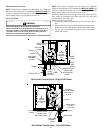
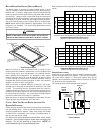
FILTER REMOVAL
Depending on the installation, differing filter arrangements can be
applied. Filters can be installed in either the central return register
or a side panel external filter rack (upflow only). A media air filter or
electronic air cleaner can be used as an alternate filter. Follow the
filter sizes given in the Recommended Minimum Filter size table to
ensure proper unit performance.