


29
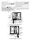
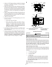
3. Inlet pressure tap connections:
a. Honeywell VR8215 Valve:
Remove the inlet pressure boss plug. Install an 1/8” NPT
hose barb fitting into the outlet pressure tap.
b. White-Rodgers 36G22 valve:
Back inlet pressure test screw (inlet pressure boss) out
one turn (counterclockwise, not more than one turn).
4. Attach a hose and manometer to the outlet pressure barb
fitting (Honeywell valve) or inlet pressure boss (White-
Rodgers valve).
5. Turn ON the gas supply.
6. Turn On power and close thermostat “R” and “W” contacts
to provide a call for heat.
7. Using a leak detection solution or soap suds, check for
leaks at outlet pressure boss plug (Honeywell valve) or
screw (White-Rodgers valve). Bubbles forming indicate a
leak. SHUT OFF GAS AND REPAIR ALL LEAKS
IMMEDIATELY!
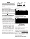
8. Measure the gas supply pressure with burners firing. Adjust
supply pressure using the Inlet Gas Supply Pressure table
shown below. If supply pressure reading differs from the
table, make necessary adjustments to pressure regulator,
gas piping size, etc., and/or consult with local gas utility.
Propane Gas
Natural Gas
Inlet Gas Supply Pressure
Minimum:5.0" W.C. Maximum :10.0" W.C.
Minimum:11.0" W.C. Maximum :13.0" W.C.
9. Turn OFF all electrical power and gas supply to the system.
10. Remove the manometer hose from the hose barb fitting or
inlet pressure boss.
11. Replace inlet pressure tap:
a. Honeywell VR8215 valve:
Remove the 1/8” NPT hose barb fitting from the inlet
pressure tap. Replace the inlet pressure boss plug and
seal with a high quality thread sealer.
b. White-Rodgers 36G22 valve:
Turn inlet pressure test screw in to seal pressure port
(clockwise, 7 in-lb minimum).
12. Retest for leaks. If bubbles form, shut down gas and repair
leaks immediately.
13. Turn ON electrical power and gas supply to the system.
14. Turn valve switch ON.
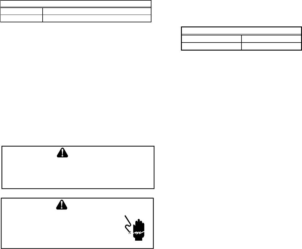
GAS MANIFOLD PRESSURE MEASUREMENT AND ADJUSTMENT
T
O
PREVENT
UNRELIABLE
OPERATION
OR
EQUIPMENT
DAMAGE
,
THE
GAS
MANIFOLD
PRESSURE
MUST
BE
AS
SPECIFIED
ON
THE
UNIT
RATING
PLATE
.O
NLY
MINOR
ADJUSTMENTS
SHOULD
BE
MADE
BY
ADJUSTING
THE
GAS
VALVE
PRESSURE
REGULATOR
.
CAUTION
HIGHVOL TAGE!
D
ISCONNECT
ALL
POWER
BEFORE
SERVICING
OR
INSTALLING
THIS
UNIT
.M
ULTIPLE
POWER
SOURCES
MAY
BE
PRESENT
.F
AILURE
TO
DO
SO
MAY
CAUSE
PROPERTY
DAMAGE
,
PERSONAL
INJURY
OR
DEATH
.
WARNING
This valve is shipped from the factory with the regulator preset (see
control label).
Consult the appliance rating plate to ensure burner manifold pres-
sure is as specified. If another outlet pressure is required, follow
these steps.
1. Turn OFF gas to furnace at the manual gas shutoff valve
external to the furnace.
2. Turn OFF all electrical power to the system.
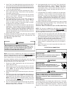
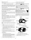
3. Outlet pressure tap connections:
a. Honeywell VR8215 valve:
Remove the outlet pressure boss plug. Install an 1/8”
NPT hose barb fitting into the outlet pressure tap.
b. White-Rodgers 36G22 valve:
Back outlet pressure test screw (outlet pressure boss)
out one turn (counterclockwise, not more than one turn).
4. Attach a hose and manometer to the outlet pressure barb
fitting (Honeywell valve) or outlet pressure boss (White-
Rodgers valve).
5. Turn ON the gas supply.
6. Turn ON power and close thermostat “R” and “W” contacts
to provide a call for heat.
7. Using a leak detection solution or soap suds, check for
leaks at outlet pressure boss plug (Honeywell valve) or
screw (White-Rodgers valve). Bubbles forming indicate a
leak. SHUT OFF GAS AND REPAIR ALL LEAKS
IMMEDIATELY!
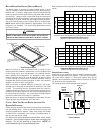
8. Measure the gas manifold pressure with burners firing.
Adjust manifold pressure using the Manifold Gas Pressure
table shown below.
Manifold Gas Pressure
Natural Gas 3.5" w.c.
Propane Gas 10.0" w.c.
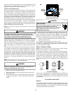
9. Remove regulator cover screw from the outlet pressure
regulator and turn screw clockwise to increase pressure or
counterclockwise to decrease pressure. Replace regulator
cover screw.
10. Turn OFF all electrical power and gas supply to the system.
11. Remove the manometer hose from the hose barb fitting or
outlet pressure boss.
12. Replace outlet pressure tap:
a. Honeywell VR8215 valve:
Remove the 1/8” NPT hose barb fitting from the outlet
pressure tap. Replace the outlet pressure boss plug and
seal with a high quality thread sealer.
b. White-Rodgers 36G22 valve: Turn outlet pressure test
screw in to seal pressure port (clockwise, 7 in-lb
minimum).
13. Turn ON electrical power and gas supply to the system.
14. Close thermostat contacts to provide a call for heat.
15. Retest for leaks. If bubbles form, SHUT OFF GAS AND
REPAIR ALL LEAKS IMMEDIATELY!
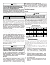
GAS INPUT RATE MEASUREMENT (NATURAL GAS ONLY)
The gas input rate to the furnace must never be greater than that
specified on the unit rating plate. To measure natural gas input
using the gas meter, use the following procedure.
1. Turn OFF the gas supply to all other gas-burning appliances
except the furnace.
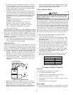
2. While the furnace is operating, time and record one
complete revolution of the smallest gas meter dial.