


5
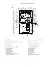
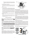
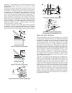
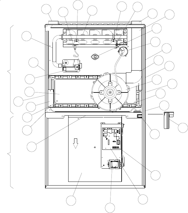
I. COMPONENT IDENTIFICATION
1 Gas Valve
2 Gas Line Entrance (Alternate)
3 Combustion Air Intake Connection / “Coupling”
4 Hot Surface Igniter
5 Burners
6 Rollout Limit
7 Flame Sensor
8 Flue Pipe Connection / “Coupling”
9 Flue Pipe (Internal)
10 Primary Limit
11 Pressure Switch
12 Gas Line Entrance
13 Rubber Elbow
14 Flue Pipe Connection (Alternate)
15 Induced Draft Blower
16 Electrical Connection Inlets (Alternate)
17 Coil Front Cover Drain Port
18 Drain Line Penetrations
19 Blower Door Interlock Switch
20 24-Volt Thermostat Connections
21 Integrated Control Module
(with fuse and diagnostic LED)
22 Transformer (40 VA)
23 Circulator Blower
24 Auxiliary Limit
25 Gas Manifold
26 Junction Box
27 Coil Front Cover
28 Drain Trap
29 Electrical Connection Inlets
Upflow/Horizontal
8
7
6
5
4
3
2
1
27
26
17
18
24
23
22
21
20
19
18
17
16
15
13
14
12
10
11
9
29
25
28
BLOWER COMPARTMENT BURNER COMPARTMENT
6