


26
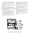
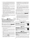
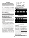
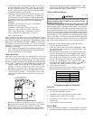
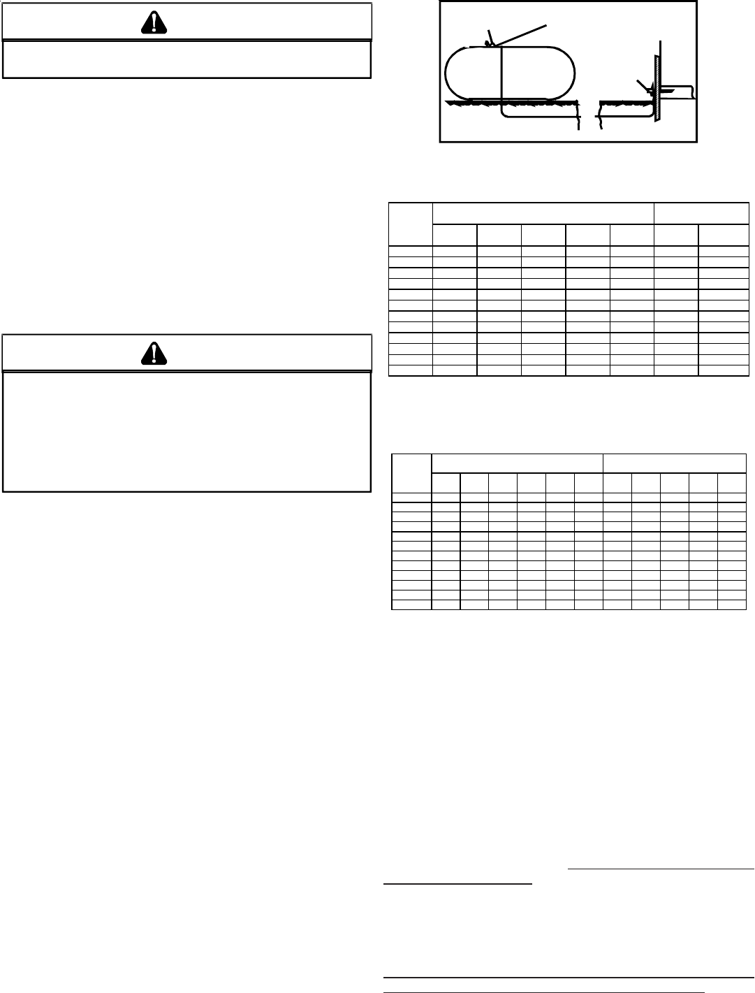
200 PSIG
Maximum
5 to 15 PSIG
(20 PSIG Max.)
Continuous
11" W.C.
Second Stage
Regulator
First Stage
Regulator
Propane Gas Installation (Typ.)
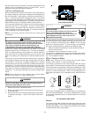
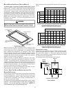
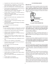
Sizing Between First and Second Stage Regulator*
Maximum Propane Capacities listed are based on 2 psig pressure drop at 10 psig setting.
Capacities in 1,000 BTU/hour.
Pipe or Nominal Pipe Size
Tubing Tubing Size, O.D. Type L Schedule 40
Length, 3/8" 1/2" 5/8" 3/4" 7/8" 1/2" 3/4"
Feet
10 730 1,700 3,200 5,300 8,300 3,200 7,500
20 500 1,100 2,200 3,700 5,800 2,200 4,200
30 400 920 2,000 2,900 4,700 1,800 4,000
40 370 850 1,700 2,700 4,100 1,600 3,700
50 330 770 1,500 2,400 3,700 1,500 3,400
60 300 700 1,300 2,200 3,300 1,300 3,100
80 260 610 1,200 1,900 2,900 1,200 2,600
100 220 540 1,000 1,700 2,600 1,000 2,300
125 200 490 900 1,400 2,300 900 2,100
150 190 430 830 1,300 2,100 830 1,900
175 170 400 780 1,200 1,900 770 1,700
200 160 380 730 1,100 1,800 720 1,500
To convert to capacities at 15 psig settings - multiply by 1.130
To convert to capacities at 5 psig settings - multiply by 0.879
Propane Gas Piping Chart I
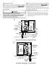
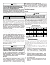
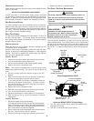
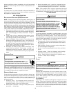
Sizing Between Single or Second Stage Regulator and Appliance*
Maximum Propane Capacities Listed are Based on 1/2" W.C. pressure drop at 11" W.C. setting.
Capacities in 1,000 BTU/hour.
Pipe or Nominal Pipe Size
Tubing Tubing Size, O.D. Type L Schedule 40
Length, 3/8" 1/2" 5/8" 3/4" 7/8" 1-1/8" 1/2" 3/4" 1" 1-1/4" 1-1/2"
Feet
10 39 92 199 329 501 935 275 567 1,071 2,205 3,307
20 26 62 131 216 346 630 189 393 732 1,496 2,299
30 21 50 107 181 277 500 152 315 590 1,212 1,858
40 19 41 90 145 233 427 129 267 504 1,039 1,559
50 18 37 79 131 198 376 114 237 448 913 1,417
60 16 35 72 121 187 340 103 217 409 834 1,275
80 13 29 62 104 155 289 89 185 346 724 1,066
100 11 26 55 90 138 255 78 162 307 630 976
125 10 24 48 81 122 224 69 146 275 567 866
150 9 21 43 72 109 202 63 132 252 511 787
200 8 19 39 66 100 187 54 112 209 439 665
250 8 17 36 60 93 172 48 100 185 390 590
*Data in accordance with NFPA pamphlet NO. 54
Propane Gas Piping Chart II
XIII. CIRCULATING AIR & FILTERS
DUCTWORK - AIR F LOW
Duct systems and register sizes must be properly designed for the
CFM and external static pressure rating of the furnace. Design the
ductwork in accordance with the recommended methods of “Air
Conditioning Contractors of America” Manual D.
Install the duct system in accordance with Standards of the Na-
tional Board of Fire Underwriters for the Installation of Air Condi-
tioning, Warm Air Heating and Ventilating Systems. Pamphlets No.
90A and 90B.
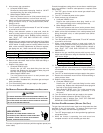
A closed return duct system must be used, with the return duct
connected to the furnace. NOTE: Ductwork must never be attached
to the back of the furnace. Flexible joints may be used for supply
and return connections to reduce noise transmission. To prevent
the blower from interfering with combustion air or draft when a
central return is used, a connecting duct must be installed be-
tween the unit and the utility room wall. Never use a room, closet,
or alcove as a return air chamber.
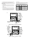
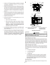
NOTE: Two side openings or a side opening and bottom opening
are required for airflow delivery of 1800 CFM and greater.
T
O
AVOID
THE
POSSIBILITY
OF
EXPLOSION
OR
FIRE
,
NEVER
USE
A
MATCH
OR
OPEN
FLAME
TO
TEST
FOR
LEAKS
.
WARNING
Check for leaks using an approved chloride-free soap and water
solution, an electronic combustible gas detector, or other approved
testing methods.
NOTE: Never exceed specified pressures for testing. Higher
pressure may damage the gas valve and cause subsequent
overfiring, resulting in heat exchanger failure.
Disconnect this unit and shutoff valve from the gas supply piping
system before pressure testing the supply piping system with pres-
sures in excess of 1/2 psig (3.48 kPa).
Isolate this unit from the gas supply piping system by closing its
external manual gas shutoff valve before pressure testing supply
piping system with test pressures equal to or less than 1/2 psig
(3.48 kPa).
PROPANE GAS TANKS AND PIPING
I
F
THE
GAS
FURNACE
IS
INSTALLED
IN
A
BASEMENT
,
AN
EXCAVATED
AREA
OR
A
CONFINED
SPACE
,
IT
IS
STRONGLY
RECOMMENDED
TO
CONTACT
A
PROPANE
SUPPLIER
TO
INSTALL
A
GAS
DETECTING
WARNING
DEVICE
IN
CASE
OF
A
GAS
LEAK
.
• S
INCE
PROPANE
GAS
IS
HEAVIER
THAN
AIR
,
ANY
LEAKING
AS
CAN
SETTLE
IN
ANY
LOW
AREAS
OR
CONFINED
SPACES
.
• P
ROPANE
GAS
ODORANT
MAY
FADE
,
MAKING
THE
GAS
U
NDETECTABLE
EXCEPT
FOR
WITH
A
WARNING
DEVICE
.
WARNING
A gas detecting warning system is the only reliable way to detect a
propane gas leak. Rust can reduce the level of odorant in propane
gas. Do not rely on your sense of smell. Contact a local propane
gas supplier about installing a gas detecting warning system. If
the presence of gas is suspected, follow the instructions on Page
4 of this manual.
All propane gas equipment must conform to the safety standards
of the National Board of Fire Underwriters, NBFU Manual 58.
For satisfactory operation, propane gas pressure must be 11 inch
w.c. at the furnace manifold with all gas appliances in operation.
Maintaining proper gas pressure depends on three main factors:
1. Vaporization rate, depending on temperature of the liquid,
and “wetted surface” area of the container or containers.
2. Proper pressure regulation. (Two-stage regulation is
recommended for both cost and efficiency).
3. Pressure drop in lines between regulators, and between
second stage regulator and the appliance. Pipe size will
depend on length of pipe run and total load of all appliances.
Complete information regarding tank sizing for vaporization, rec-
ommended regulator settings, and pipe sizing is available from
most regulator manufacturers and propane gas suppliers.
Since propane gas will quickly dissolve white lead and most stan-
dard commercial compounds, special pipe dope must be used.
Shellac-based compounds resistant to the actions of liquefied pe-
troleum gases such as Gasolac
®
, Stalactic
®
, Clyde’s
®
or John
Crane
®
are satisfactory.
Refer to the following illustration for typical propane gas installa-
tions.