


28
HORIZONTAL I NSTALLATIONS
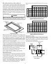
Filters must be installed in either the central return register or in the
return air duct work.
XIV. STARTUP PROCEDURE & ADJUSTMENT
Furnace must have a 115 VAC power supply properly connected
and grounded. Proper polarity must be maintained for correct op-
eration. In addition to the following start-up and adjustment items,
refer to further information in Section XVI, Operational Checks.
HEAT ANTICIPATOR S ETTING
The heat anticipator in the room thermostat must be correctly ad-
justed to obtain the proper number of cycles per hour and to pre-
vent “overshooting” of the setting. Set the heat anticipator setting to
0.7 amps. Follow the thermostat manufacturer’s instructions on
how to adjust the heat anticipator setting.
DRAIN TRAP PRIMING
The drain trap must be primed prior to furnace startup. To prime, fill
the drain trap with water. This ensures proper furnace drainage
upon startup and prohibits the possibility of flue gases escaping
through the drain system.
FURNACE OPERATION
Purge gas lines of air prior to startup. Be sure not purge lines into
an enclosed burner compartment.
Check for leaks using an approved chloride-free soap and water
solution, an electronic combustible gas detector, or other approved
method. Verify that all required kits (propane gas, high altitude,
etc.) have been appropriately installed.
FURNACE STARTUP
1. Close the manual gas shutoff valve external to the furnace.
2. Turn off the electrical power to the furnace.
3. Set the room thermostat to the lowest possible setting.
4. Remove the burner compartment door.
NOTE: This furnace is equipped with an ignition device which
automatically lights the burner. Do not try to light the burner by
hand.
5. Move the furnace gas valve manual control to the OFF
position.
6. Wait five minutes then smell for gas. Be sure to check near
the floor as some types of gas are heavier than air.
7. If you smell gas after five minutes, immediately follow the
instructions on page 4 of this manual. If you do not smell
gas after five minutes, move the furnace gas valve manual
control to the ON position.
8. Replace the burner compartment door.
9. Open the manual gas shutoff valve external to the furnace.
10. Turn on the electrical power to the furnace.
11. Adjust the thermostat to a setting above room temperature.
12. After the burners are lit, set the thermostat to desired
temperature.
FURNACE SHUTDOWN
1. Set the thermostat to the lowest setting.
The integrated control will close the gas valve and extinguish
flame. Following a 15 second delay, the induced draft blower
will be de-energized. After a 150-second delay period (fixed),
the circulator blower will be de-energized.
2. Remove the burner compartment door and move the furnace
gas valve manual control to the OFF position.
3. Close the manual gas shutoff valve external to the furnace.
4. Replace the burner compartment door.
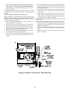
GAS SUPPLY PRESSURE MEASUREMENT
CAUTION
T
O
PREVENT
UNRELIABLE
OPERATION
OR
EQUIPMENT
DAMAGE
,
THE
INLET
GAS
SUPPLY
PRESSURE
MUST
BE
AS
SPECIFIED
ON
THE
UNIT
RATING
PLATE
WITH
ALL
OTHER
HOUSEHOLD
GAS
FIRED
APPLIANCES
OPERATING
.
HIGHVOL TAGE!
D
ISCONNECT
ALL
POWER
BEFORE
SERVICING
OR
INSTALLING
THIS
UNIT
.M
ULTIPLE
POWER
SOURCES
MAY
BE
PRESENT
.F
AILURE
TO
DO
SO
MAY
CAUSE
PROPERTY
DAMAGE
,
PERSONAL
INJURY
OR
DEATH
.
WARNING
The line pressure supplied to the gas valve must be within the
range specified below. The supply pressure can be measured at
the gas valve inlet pressure tap or at a hose fitting installed in the
gas piping drip leg. The supply pressure must be measured with
the unit OFF. To measure inlet pressure, use the following proce-
dure.
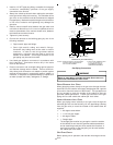
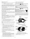
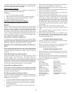
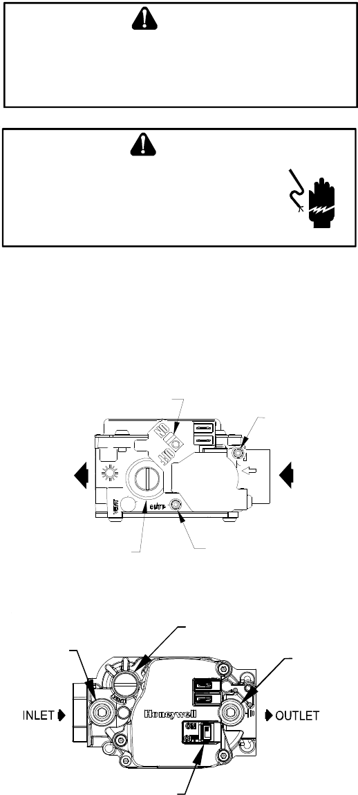
Pressure Regulator
Adjustment
(Under Cap Screw)
Gas Valve
On/Off
Selector
Switch
INLET
OUTLET
Inlet Pressure
Tap
Outlet Pressure
Tap
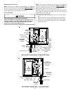
White-Rodgers Model 36G22
Gas Valve On/Off
Selector Switch
Inlet
Pressure
Tap
Pressure Regulator
(under cap screw)
Outlet
Pressure
Tap
Honeywell Model VR8215 (Single-Stage)
1. Turn OFF gas to furnace at the manual gas shutoff valve
external to the furnace.
2. Turn OFF all electrical power to the system.