


11
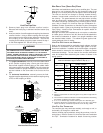
5. When directly communicating with the outdoors, the single open-
ing shall have a minimum free area of 1 square inch per 3,000
BTU per hour of total input rating of all equipment in the enclo-
sure.
5.3.4 Specially Engineered Installations:
The requirements of 5.3.3 shall not necessarily govern when special
engineering, approved by the authority having jurisdiction, provides an
adequate supply of air for combustion, ventilation, and dilution of flue
gases.
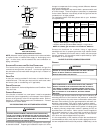
5.3.5 Louvers and Grilles:
In calculating free area in 5.3.3, consideration shall be given to the block-
ing effect of louvers, grilles or screens protecting openings. Screens used
shall not be smaller than 1/4 inch mesh. If the area through a design of
louver or grille is known, it should be used in calculating the size of
opening required to provide the free area specified. If the design and free
area is not known, it may be assumed that wood louvers will have 20-25
percent free area and metal louvers and grilles will have 60-75 percent
free area. Louvers and grilles shall be fixed in the open position or
interlocked with the equipment so that they are opened automatically
during equipment operation.
5.3.6 Special Conditions Created by Mechanical Exhausting or Fire-
places:
Operation of exhaust fans, ventilation systems, clothes dryers, or fire-
places may create conditions requiring special attention to avoid unsat-
isfactory operation of installed gas utilization equipment. Air from
Inside Building. See 5.3.3-a.
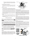
VI. INSTALLATION POSITIONS
NOTE: This furnace is shipped from the factory as a Dedicated
Upflow. A “Blocked Drain Kit” (0270K00012) is available and MUST
BE USED if the furnace is installed Horizontal Left or Horizontal
Right.
This furnace may be installed in an upright position or horizontal
on either the left or right side panel. Do not install this furnace on
its back. For upright upflow furnaces, return air ductwork may be
attached to the side panel(s) and/or basepan. For horizontal upflow
furnaces, return air ductwork must be attached to the basepan.
NOTE: Ductwork must never be attached to the back of the furnace.
Contact your distributor for proper airflow requirements and num-
ber of required ductwork connections. Refer to “Recommended
Installation Positions” figure for appropriate installation positions,
ductwork connections, and resulting airflow arrangements.
VII. HORIZONTAL APPLICATIONS & CONSIDERATIONS
NOTE: This furnace is shipped from the factory as a Dedicated
Upflow. A “Blocked Drain Kit” is available and MUST BE USED if the
furnace is installed Horizontal Left or Horizontal Right. Check the
Serial/ Rating Plate on the furnace for the Kit P/N.
GENERAL
Horizontal applications, in particular, may dictate many of the
installation’s specifics such as airflow direction, ductwork connec-
tions, flue and combustion air pipe connections, etc. The basic
application of this furnace as a horizontal furnace differs only slightly
from an upright installation. When installing a furnace horizontally,
additional consideration must be given to the following:
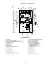
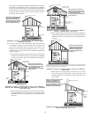
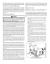
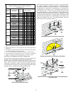
ALTERNATE VENT/FLUE
LOCATION
FURNACE MUST BE LEVEL
FROM END TO END
FURNACE MUST BE LEVEL
OR SLIGHTLY TILTED FORWARD
WITH THE DOORS 0" - 3/4"
BELOW THE BACK PANEL
DRAIN LINE WITH 1/4" PER FOOT
DOWNWARD SLOPE
36" MINIMUM SERVICE
CLEARANCE REQUIRED
FURNACE MUST BE SUPPORTED
AT BOTH ENDS AND MIDDLE
DRAIN PAN
GAS LINE WITH
DRIP LEG (3" MINIMUM)
4 3/4" MINIMUM
DRAIN TRAP
CLEARANCE
Horizontal Furnace
DRAIN TRAP AND LINES
In horizontal applications the condensate drain trap is secured to
the furnace side panel, suspending it below the furnace. A mini-
mum clearance of 4 3/4 inches below the furnace must be pro-
vided for the drain trap. Additionally, the appropriate downward
piping slope must be maintained from the drain trap to the drain
location. Refer to Section X, Condensate Drain Trap and Lines for
further details. If the drain trap and drain line will be exposed to
temperatures near or below freezing, adequate measures must
be taken to prevent condensate from freezing.
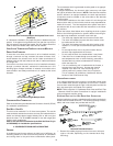
LEVELING
Leveling ensures proper condensate drainage from the heat ex-
changer and induced draft blower. For proper flue pipe drainage,
the furnace must be level lengthwise from end to end. The furnace
should also be level from back to front or have a slight tilt with the
access doors downhill (approximately 3/4 inches) from the back
panel. The slight tilt allows the heat exchanger condensate, gen-
erated in the recuperator coil, to flow forward to the recuperator coil
front cover.
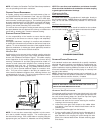
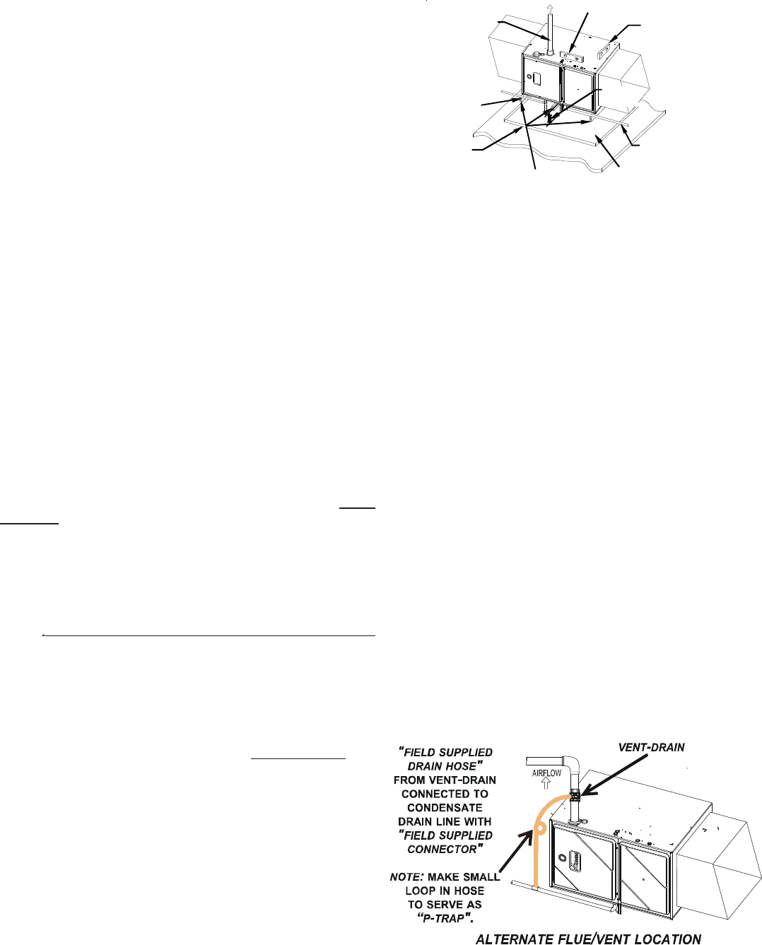
ALTERNATE V ENT/FLUE C ONNECTION
In horizontal installations provisions for alternate flue piping are
available for upflow furnaces with left discharge. This configura-
tion allows the flue piping to be run vertically through the furnace.
Refer to the “Recommended Installation Positions” figure for fur-
ther detail. The standard piping connections may also be used in
these positions. Refer to Section IX, Vent/Flue Pipe and Combus-
tion Air Pipe for details concerning the conversion to the alternate
vent/flue connections.
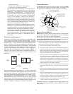
When using the horizontal alternate vent configuration, you must
use the RF000142 vent drain kit. See following illustration.