


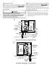
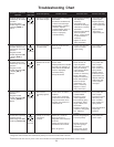

35
• Circulator blower runs
continuously. No furnace
operation.
• Integrated control
module diagnostic LED
is flashing FOUR (4)
flashes.
• Primary or auxiliary
limit circuit is open.
• Check primary/auxiliary
limit. Replace if
necessary.
• Check filters and
ductwork for blockage.
Clean filters or remove
obstruction.
• Check circulator blower
speed and perfor-
mance. Correct speed
or replace blower if
necessary.
• Tighten or correct
wiring connection.
• Turn power OFF
prior to repair.
• Replace primary/
auxiliary limit with
proper replacement
part.
• Replace blower
with correct
replacement part.
4
4 FLASHES
• Faulty primary or auxiliary
limit switch.
• Insufficient conditioned air
over the heat exchanger.
Blocked filters, restrictive
ductwork, improper
circulator blower speed, or
failed circulator blower.
• Loose or improperly
connected wiring.
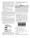
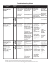
Fault Description(s) Possible Causes Corrective Action Cautions and Notes
Symptoms of Abnormal
Operation
Associated
LED Code
2
• Normal furnace
operation.
• Integrated control
module diagnostic LED
is flashing SEVEN (7)
flashes.
• Flame sense
microamp signal is
low.
• Sand flame sensor if
coated/oxidized.
• Inspect for proper
sensor alignment.
• Check inlet air piping
for blockage, proper
length, elbows, and
termination.
• Compare current gas
pressure to rating plate
info. Adjust as
needed.
• Turn power OFF
prior to repair.
• Sand flame sensor
with emery clot.
• See “Vent/Flue
Pipe” section for
piping details.
• See rating plate for
proper gas
pressure.
7
7 FLASHES
• Flame sensor is coated/
oxidized.
• Flame sensor incorrectly
positioned in burner flame.
• Lazy burner flame due to
improper gas pressure or
combustion air.
• Induced draft blower and
circulation blower runs
continuously. No furnace
operation.
• Integrated control
module diagnostic LED
is flashing FIVE (5)
flashes.
• Flame sensed with
no call for heat.
• Correct short at flame
sensor or in flame
sensor wiring.
• Turn power OFF
prior to repair.
5
5 FLASHES
• Short to ground in flame
sense circuit.
• Circulator blower runs
continuously. No furnace
operation.
• Integrated control
module diagnostic LED
is flashing SIX (6)
flashes.
• Rollout limit circuit is
open.
• Check burners for
proper alignment.
• Check flue and air inlet
piping for blockage,
proper length, elbows,
and termination.
Correct as necessary.
• Check rollout limit.
Replace if necessary.
• Check induced draft
blower for proper
performance. Re-
place, if necessary.
• Tighten or correct
wiring connection.
• Turn power OFF
prior to repair.
• See “Vent/Flue
Pipe” section for
piping details.
• Replace rollout
limit with correct
replacement part.
• Replace induced
draft blower with
correct replace-
ment part.
6
6 FLASHES
• Flame rollout.
• Misaligned burners, blocked
flue and/or air inlet pipe, or
failed induced draft blower.
• Loose or improperly
connected wiring.
• Faulty rollout limit.
• Furnace fails to operate.
• Integrated control
module diagnostic LED
is flashing continuously.
• Polarity of 115 or 24
volt power is
reversed.
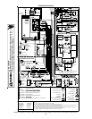
• Review wiring diagram
to correct polarity.
• Reverse orange and
gray wires going to
transformer.
• Verify proper ground.
Correct if necessary.
• Turn power OFF
prior to repair.
C
CONTINUOUS/
RAPID FLASH
• Polarity of 115 volt AC
power to furnace or
integrated control module is
reversed.
• Orange and gray wires to
transformer are reversed.
• Poor unit ground.
Troubleshooting Chart
1
Integrated control module will automatically attempt to reset from lockout after one hour.
2
LED Flash code will cease if power to the control module is interrupted through the disconnect or door switch.