


14
NOTE: In Canada, the Canadian Fuel Gas Code takes precedence
over the preceding termination restrictions.
CANADIAN V ENTING REQUIREMENTS
In Canada, venting must conform to the requirements of the cur-
rent CAN/CSA-B149.1-05 Installation Code. Use only CSA-listed,
ULC-S636 compliant two-three-inch diameter PVC or ABS pipe,
solvent cement, and fittings throughout. The certified piping should
be clearly marked with the ULC Std “S636” on the pipe and fittings.
Carefully follow the pipe manufacturers’ instructions for cutting,
cleaning, and solvent cementing PVC and/or ABS.
The vent can be run through an existing unused chimney provided
the space between the vent pipe and the chimney is insulated and
closed with a weather-tight, corrosion-resistant flashing.
STANDARD FURNACE C ONNECTIONS
It is the responsibility of the installer to ensure that the piping
connections to the furnace are secure, airtight, and adequately
supported.
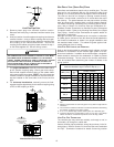
As shipped, attachment “couplings” for vent/flue and combustion
air intake pipe connections are provided on the furnace’s top cover
(upflow). To use the standard connections, field supplied vent/flue
pipe and combustion air intake pipe (when applicable) should be
secured directly to the furnace at these locations.
VENT/FLUE PIPE
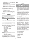
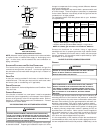
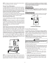
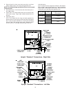
Vent/flue pipe can be secured to the vent/flue coupling using the
rubber coupling and worm gear hose clamps provided with this
furnace (see “Standard Connections” figure). The rubber coupling
allows separation of the vent/flue pipe from the furnace during
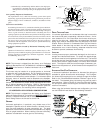
servicing. Combustion Air and Vent piping should be routed in a
manner to avoid contact with refrigerant lines, metering devices,
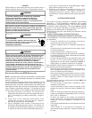
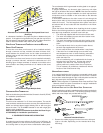
condensate drain lines, etc. If necessary, clearances may be
increased by utilizing two 45 deg. Long-Sweep Elbows and creat-
ing an “S” joint to provide additional space at connection loca-
tions. This joint can be rotated on the fitting to establish maxi-
mum clearance between refrigerant lines, metering devices, and
condensate drain lines, etc. This joint is the equivalent of one 90
deg. elbow when considering elbow count.
45 DEGREE
LONG-SWEEP
ELBOWS
V
E
N
T
Increased Clearance Configuration
NOTE: Do not use other commercially available “no hub connec-
tors” due to possible material conflicts. The vent/flue pipe can
also be secured using a PVC or ABS elbow or coupling using the
appropriate glue (see Section IX, Materials and Joining Methods.
NOTE: For non-direct vent installations, a minimum of one 90°
elbow should be installed on the combustion air intake coupling
to guard against inadvertent blockage.
COMBUSTION AIR PIPE
DIRECT V ENT I NSTALLATIONS
On upflow units secure the combustion air intake pipe directly to
the air intake coupling. NOTE: Because of probable material con-
flicts, do not use other commercially available “no hub connec-
tors”.
NON-DIRECT V ENT I NSTALLATIONS
A minimum of one 90° elbow should be installed on the combus-
tion air intake “coupling” to guard against inadvertent blockage.
RUBBER
COUPLING
WITH WORM
GEAR CLAMPS
COMBUSTION
AIR PIPE
(DIRECT VENT ONLY)
VENT/FLUE
PIPE
(NON-DIRECT VENT)
90 PVC
ELBOW
(NON-DIRECT VENT)
STANDARD CONNECTIONS
OR
UPFLOW
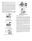
ALTERNATE F URNACE CONNECTIONS
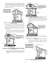
If the standard locations are undesirable for a specific installation,
alternate side panel locations are available for vent/flue pipe con-
nections. These locations may be of particular benefit to upright
upflow installations requiring additional access to an A coil or to
horizontal installations desiring vent/flue piping run vertically from
the side of the cabinet.
NOTE: Standard and alternate locations can be combined (i.e., an
installation may use the standard combustion air intake location
but use the alternate vent/flue location), if needed.
E
DGES
OF
SHEET
METAL
HOLES
MAY
BE
SHARP
. U
SE
GLOVES
AS
A
PRECAUTION
WHEN
REMOVING
HOLE
PLUGS
.
WARNING
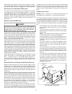
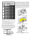
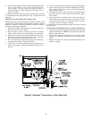
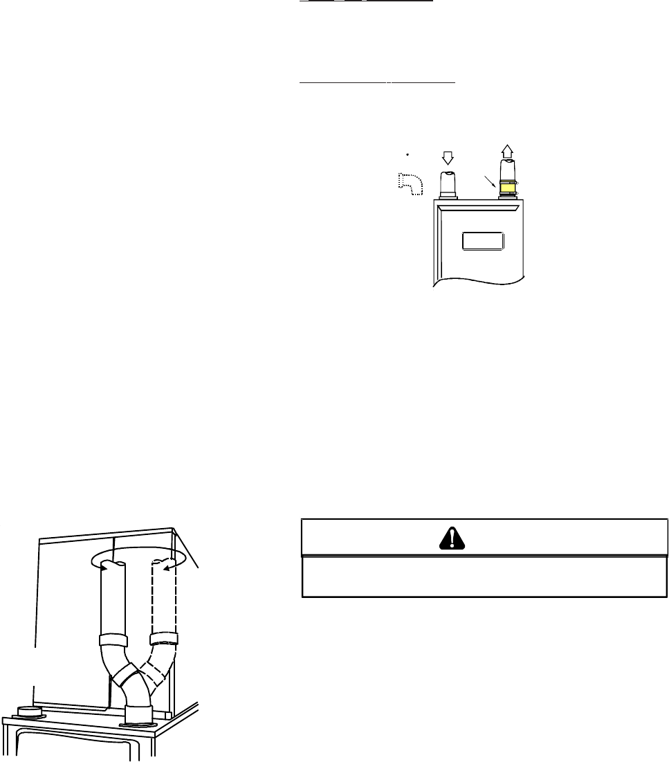
ALTERNATE VENT/FLUE LOCATION
The alternate vent/flue location is the large hole directly in line with
the induced draft blower outlet. To use the alternate vent/flue loca-
tion refer to the following steps, the “Vent/Flue Pipe Cuts” figure,
and the “Alternate Vent/Flue Location” figure.
1. Remove and save the four screws securing the vent/flue
coupling to the furnace top panel.
2. Loosen the worm gear hose clamps on the rubber elbow
and detach it from both the induced draft blower and the
vent/flue pipe.
3. Remove the vent/flue pipe from the furnace.
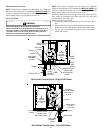
4. Cut the vent/flue pipe 3.75 inches from the flanged end of
the pipe. See Vent/Flue Pipe Cuts figure. The section of
pipe attached to the coupling will reach through the side
panel to the induced draft blower. Discard remaining pipe
and elbows.