


15
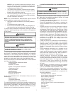
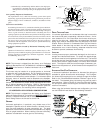
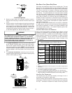
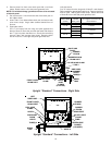
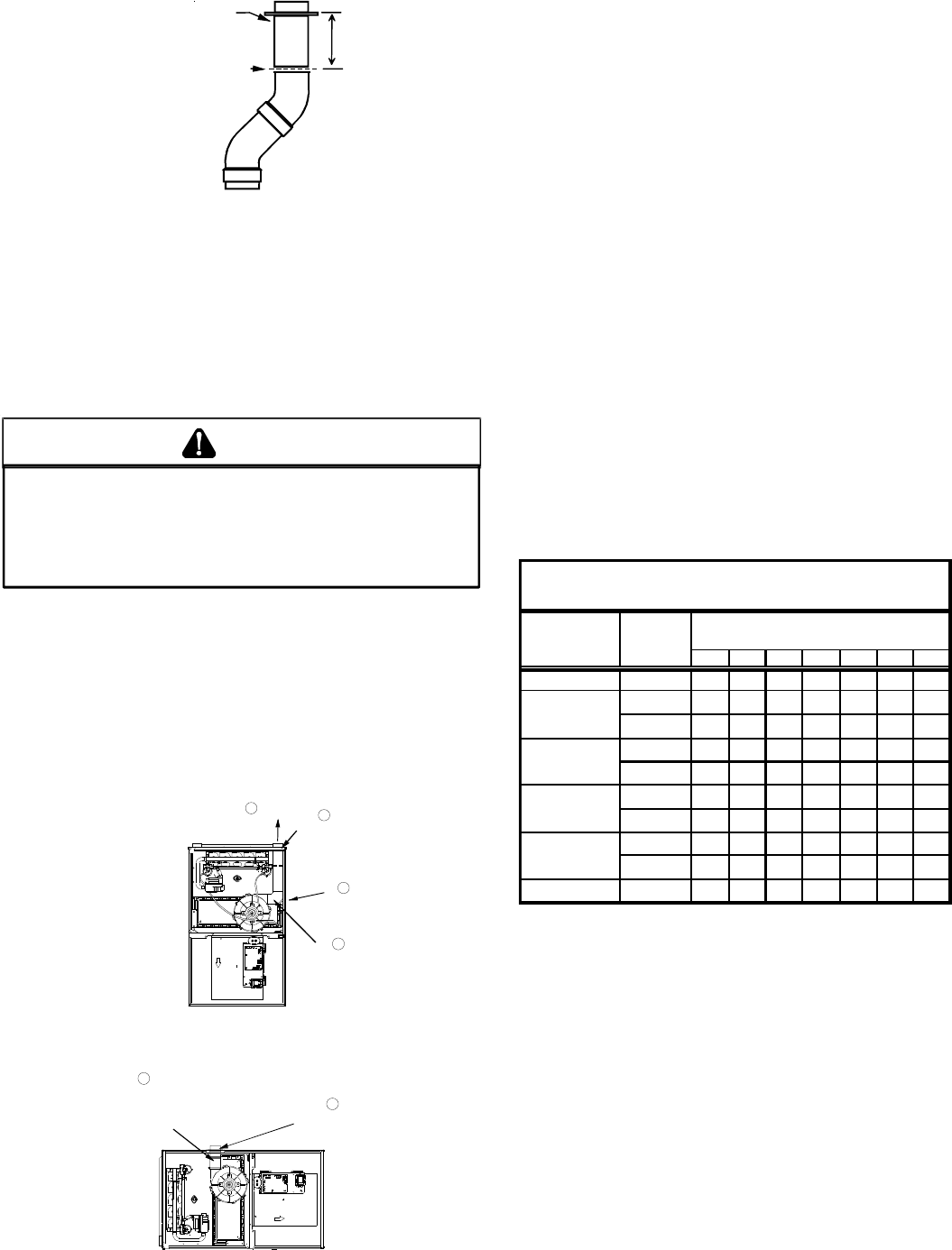
FLANGE
CUT HERE
3.75"
Vent/Flue Pipe Cuts
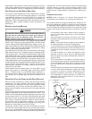
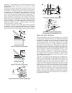
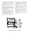
5. Remove plastic plug from alternate vent/flue location.
Relocate and install plug in standard vent/flue location (top
cover).
6. Insert cut section of vent/flue pipe and coupling into alternate
vent/flue location. Using a rubber coupling and worm gear
hose clamps from the drain kit bag, attach the vent/flue pipe
and coupling to the induced draft blower. Secure the
coupling to the cabinet using the screws removed in step 1
or with field-supplied 3/8” #8 self drilling screws.
T
HE
RUBBER
ELBOW
IS
NOT
DESIGNED
TO
SUPPORT
A
LOAD
. W
HEN
THE
RUBBER
ELBOW
IS
MOUNTED
EXTERNALLY
TO
THE
FURNACE
CABINET
,
EXTREME
CARE
MUST
BE
TAKEN
TO
ADEQUATELY
SUPPORT
FIELD
-
SUPPLIED
VENT
/
FLUE
PIPING
,
AS
DAMAGE
CAN
RESULT
IN
LEAKS
CAUSING
BODILY
INJURY
OR
DEATH
DUE
TO
EXPOSURE
TO
FLUE
GASES
,
INCLUDING
CARBON
MONOXIDE
.
WARNING
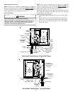
7. For upright installations, externally mount the rubber elbow
to the vent/flue coupling using a worm gear hose clamp.
Secure field supplied vent/flue piping to the rubber elbow
using a worm gear hose clamp. NOTE: Use of the alternate
vent/flue location for upright installations, requires the drain
trap be installed on the same side of the unit as the flue
pipe.
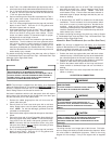
8. For horizontal installations, externally secure the field-
supplied vent/flue pipe directly to the vent/flue coupling using
a PVC or ABS coupling or elbow.
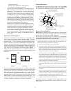
UPFLOW
REMOVE
4 SCREWS
3
REMOVE
PIPE
2
DETACH RUBBER
ELBOW FROM
ID BLOWER AND
VENT/FLUE
PIPE
5
REMOVE
AND RELOCATE
1
UPFLOW/HORIZONTAL
6
SECURE TO
ID BLOWER WITH
RUBBER COUPLING
AND HOSE
CLAMPS
6
SECURE TO
CABINET WITH
SCREWS
Alternate Vent/Flue Location
NON-DIRECT VENT (SINGLE PIPE) PIPING
Non-direct vent installations require only a vent/flue pipe. The vent
pipe can be run horizontally with an exit through the side of the
building or run vertically with an exit through the roof of the building.
The vent can also be run through an existing unused chimney;
however, it must extend a minimum of 12 inches above the top of
the chimney. The space between the vent pipe and the chimney
must be closed with a weather-tight, corrosion-resistant flashing.
For details concerning connection of the vent/flue pipe to the fur-
nace, refer to Section IX, Vent/Flue Pipe and Combustion Air -
Standard Furnace Connections or Alternate Furnace Connections
for specific details. Refer to the following Non-Direct Vent (Single
Pipe) Piping - Vent/Flue Pipe Terminations for specific details on
termination construction.
Although non-direct vent installations do not require a combustion
air intake pipe, a minimum of one 90° elbow should be attached to
the furnace’s combustion air intake if: an upright installation uses
the standard intake location. This elbow will guard against inad-
vertent blockage of the air intake.
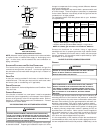
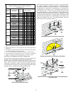
VENT/FLUE PIPE LENGTHS AND DIAMETERS
Refer to the following table for applicable length, elbows, and pipe
diameter for construction of the vent/flue pipe system of a non-
direct vent installation. In addition to the vent/flue pipe, a single 90°
elbow should be secured to the combustion air intake to prevent
inadvertent blockage. The tee used in the vent/flue termination
must be included when determining the number of elbows in the
piping system.
Pipe
Size
(4)
(
in.
)
2
3
4
5
6
78
045_3 2 or 2 1/2 68 65 62 59 56 53 50
2 or 2 1/236333027242118
3 68656259565350
2 or 2 1/255524946434037
3 68656259565350
2 or 2 1/237343128252219
3 68656259565350
2 or 2 1/239363330272421
3 68656259565350
115_5 3 68656259565350
Non-Direct Vent (Single Pipe)
Maximum Allowable Length of Vent/Flue Pipe (ft)
(1) (2)
090_5
Number of Elbows
(3) (5)
Models
(kBTU_Tons)
070_3
090_4
070_4
1) One 90° elbow should be secured to the combustion air intake connec-
tion.
2) Minimum requirement for each vent pipe is five (5) feet in length and one
elbow/tee.
3) Tee used in the vent/flue termination must be included when determining
the number of elbows in the piping system.
4) 2 1/2” or 3” diameter pipe can be used in place of 2” diameter pipe.
5) Increased Clearance Configurations using (2) 45 deg.
Long Sweep
elbows should be considered equivalent to one 90 deg. elbow.
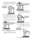
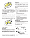
VENT/FLUE PIPE TERMINATIONS
The vent/flue pipe may terminate vertically, as through a roof, or
horizontally, as through an outside wall.
Vertical vent/flue pipe terminations should be as shown in the fol-
lowing figure. Refer to Section IX, Vent/Flue Pipe and Combustion
Air Pipe - Termination Locations for details concerning location