


25
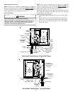
ALTERNATE
GAS LINE
LOCATION
PLUG IN
ALTERNATE
GAS LINE
HOLE
PIPE UNION
MANIFOLD
BURNERS
GAS VALVE
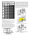
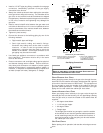
HORIZONTAL [UPFLOW MODEL]
MANUAL SHUT-OFF VALVE
(UPSTREAM FROM GROUND
JOINT PIPE UNION)
DRIP LEG
GROMMET IN STANDARD
GAS LINE HOLE
DRAIN TRAP
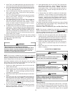
ALTERNATE GAS
LINE LOCATION
MANIFOLD
PLUG IN ALTERNATE
GAS LINE HOLE
GAS VALVE
GROUND JOINT
PIPE UNION
BURNERS
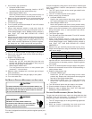
NOTES
:
1.
WHEN
GAS
LINE
IS
IN
THE
ALTERNATE
LOCATION
,
SWAP
THE
POSITION
OF
THE
PLUG
AND
GROMMET
.
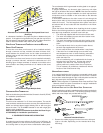
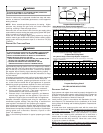
MANUAL
SHUT OFF VALVE
(UPSTREAM FROM
GROUND JOINT
PIPE UNION)
GROMMET
IN STANDARD
GAS LINE HOLE
HEIGH T REQUIRED
BY LOCAL CODE
DRIP LEG
UPFLOW
2. DRIP LEG MAY TERMINATE WITH
A 1/2" X 1/8" PIPE PLUG TO
ACCOMMODATE LINE GAS
PRESSURE MEASUREMENT.
GROUND JOINT
PIPE UNION
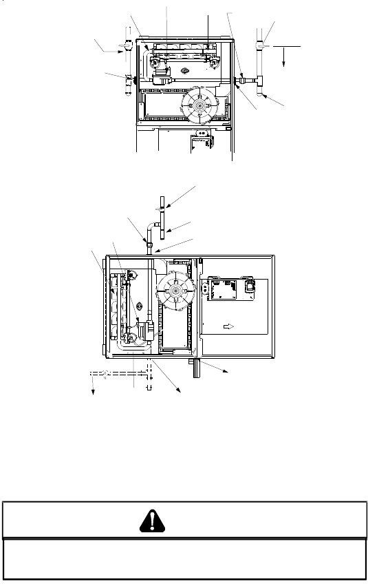
Gas Piping Connections
E
DGES
OF
SHEET
METAL
HOLES
MAY
BE
SHARP
. U
SE
GLOVES
AS
A
PRECAUTION
WHEN
REMOVING
HOLE
PLUGS
.
WARNING
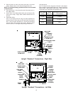
DIRECT/STANDARD INLET PIPING
When gas piping enters directly to the gas valve through the stan-
dard inlet hole, the installer must supply straight pipe with a ground
joint union to reach the exterior of the furnace. The rigid pipe must
be long enough to reach the outside of the cabinet to seal the
grommet cabinet penetration. A semi-rigid connector to the gas
piping can be used outside the cabinet per local codes.
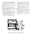
INDIRECT/ALTERNATE INLET PIPING
When gas piping enters indirectly to the gas valve through the
alternate gas inlet hole the following 1/2 inch pipe fittings (starting
from the gas valve) to reach the outside of the cabinet must be
supplied:
• 1 - 90 degree street elbow.
• 1 - 2-1/2 inch pipe nipple.
• 1 - 90 degree elbow.
• 1 - Straight pipe
The straight pipe must be long enough to reach the outside
of the cabinet so as to seal the grommet cabinet penetration
and to install the ground joint union outside of the cabinet. A
semi-rigid connector to the gas piping can be used outside
the cabinet per local codes.
GAS PIPING CHECKS
Before placing unit in operation, leak test the unit and gas connec-
tions.
• Install a 1/8" NPT pipe plug fitting, accessible for test gage
connection, immediately upstream of the gas supply
connection to the furnace.
• Always use a back-up wrench when making the connection
to the gas valve to keep it from turning. The orientation of the
gas valve on the manifold must be maintained as shipped
from the factory. Maximum torque for the gas valve connection
is 375 in-lbs; excessive over-tightening may damage the
gas valve.
• Install a manual shutoff valve between the gas meter and
unit within six feet of the unit. If a union is installed, the union
must be downstream of the manual shutoff valve, between
the shutoff valve and the furnace.
• Tighten all joints securely.
• Connect the furnace to the building piping by one of the
following methods:
– Rigid metallic pipe and fittings.
– Semi-rigid metallic tubing and metallic fittings.
Aluminum alloy tubing must not be used in exterior
locations. In order to seal the grommet cabinet
penetration, rigid pipe must be used to reach the
outside of the cabinet. A semi-rigid connector to the
gas piping may be used from there.
• Use listed gas appliance connectors in accordance with
their instructions. Connectors must be fully in the same
room as the furnace.
• Protect connectors and semirigid tubing against physical
and thermal damage when installed. Ensure aluminum-
alloy tubing and connectors are coated to protect against
external corrosion when in contact with masonry, plaster, or
insulation, or subjected to repeated wetting by liquids such
as water (except rain water), detergents, or sewage.