


16
MIN.
12"
FROM
WALL
12"
TO GROUND OR
HIGHEST ANTICIPATED
SNOW LEVEL
WALL
INSIDE
OUTSIDE
TEE
or
90°ELBOW
TURNED
DOWN
COUPLING
ELBOW OR
COUPLING
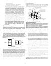
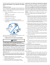
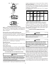
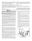
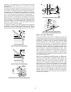
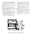
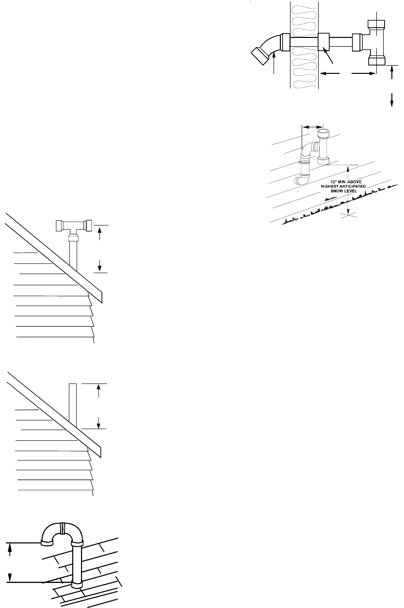
Horizontal Termination (Single Pipe)
VENT/FLUE TEE
or
90° ELBOW TURNED
DOWN
12" MIN.
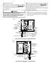
Horizontal Termination (Single Pipe)
Above Highest Anticipated Snow Level
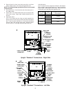
DIRECT VENT (DUAL PIPE) PIPING
Direct vent installations require both a combustion air intake and
a vent/flue pipe. The pipes may be run horizontally and exit through
the side of the building or run vertically and exit through the roof of
the building. The pipes may be run through an existing unused
chimney; however, they must extend a minimum of 12 inches
above the top of the chimney. The space between the pipes and
the chimney must be closed with a weather tight, corrosion resis-
tant flashing. Both the combustion air intake and a vent/flue pipe
terminations must be in the same atmospheric pressure zone.
Refer to Section IX, Vent/Flue and Combustion Air Pipe - Termi-
nation Locations or Concentric Vent Termination for specific de-
tails on termination construction. For details concerning connec-
tion of pipes to the furnace, refer to the Section IX, Vent/Flue Pipe
and Combustion Pipe - Standard Furnace Connections or Alter-
nate Furnace Connections.
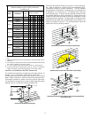
VENT/FLUE AND COMBUSTION AIR PIPE LENGTHS AND DIAMETERS
Refer to the following table for applicable length, elbows, and
pipe diameter for construction of the vent/flue and combustion air
intake pipe systems of a direct vent (dual pipe) installation. The
number of elbows tabulated represents the number of elbows
and/or tees in each (Vent/Flue & Combustion Air Intake) pipe.
Elbows and/or tees used in the terminations must be included
when determining the number of elbows in the piping systems.
If the combustion air intake pipe is to be installed above a finished
ceiling or other area where dripping of condensate will be objec-
tionable, insulation of the combustion air pipe may be required.
Use 1/2” thick closed cell foam insulation such as Armaflex or
Insultube where required.
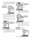
restrictions. The penetration of the vent through the roof must be
sealed tight with proper flashing such as is used with a plastic
plumbing vent.
Horizontal vent/flue pipe terminations should be as shown in the
following figure. Refer to Section IX, Vent/Flue Pipe and Combus-
tion Air Pipe - Termination Locations for details concerning loca-
tion restrictions. A 2 3/8” diameter wall penetration is required for
2” diameter pipe. A 3” diameter hole is required for a 2 1/2” pipe
and a 3 1/2” diameter hole is required for 3” diameter pipe. To
secure the pipe passing through the wall and prohibit damage to
piping connections, a coupling should be installed on either side
of the wall and solvent cemented to a length of pipe connecting
the two couplings. The length of pipe should be the wall thick-
ness plus the depth of the socket fittings to be installed on the
inside and outside of the wall. The wall penetration should be
sealed with silicone caulking material.
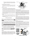
In a basement installation, the vent/flue pipe can be run between
joist spaces. If the vent pipe must go below a joist and then up
into the last joist space to penetrate the header, two 45° elbows
should be used to reach the header rather than two 90° elbows.
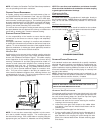
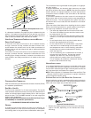
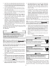
12 " Min To
Roof Or
Highest Anticipated
Snow Level
TEE
Vertical Termination (Single Pipe)
12 " Min To
Roof Or
Highest Anticipated
Snow Level
Vertical Termination (Single Pipe)
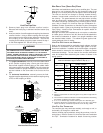
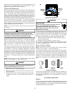
12" MIN.
TO ROOF OR
HIGHEST
ANTICIPATED
SNOW LEVEL
90º
MEDIUM RADIUS
ELBOWS
Alternate Vertical Termination (Single Pipe)