


17
Pipe
Size
(4)
(in.) 2345678
Standard 2 or 2 1/2 68 65 62 59 56 53 50
Alternate 2 or 2 1/255524946434037
Standard 2 or 2 1/2 36 33 30 27 24 21 18
Alternate 2 or 2 1/2 23 20 17 14 11 8 5
Standard 3 68 65 62 59 56 53 50
Alternate 3 55 52 49 46 43 40 37
Standard 2 or 2 1/2 55 52 49 46 43 40 37
Alternate 2 or 2 1/242393633302724
Standard 3 68 65 62 59 56 53 50
Alternate 3 55 52 49 46 43 40 37
Standard 2 or 2 1/2 37 34 31 28 25 22 19
Alternate 2 or 2 1/2 24 21 18 15 12 9 6
Standard 3 68 65 62 59 56 53 50
Alternate 3 55 52 49 46 43 40 37
Standard 2 or 2 1/2 39 36 33 30 27 24 21
Alternate 2 or 2 1/2262320171411 8
Standard 3 68 65 62 59 56 53 50
Alternate 3 55 52 49 46 43 40 37
Standard 3 68 65 62 59 56 53 50
Alternate 3 55 52 49 46 43 40 37
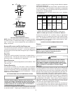
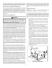
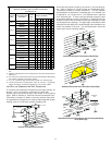
Direct Vent (Dual Pipe)
Maximum Allowable Length of Vent/Flue & Combustion
Air Intake Pipe (ft)
Unit Input
(Btu)
Number of Elbows
(1)(2)(3)(5)
115_5
Vent/Flue/Air Intake
Te rmination
045_3
090_4
070_4
070_3
090_5
1) One 90° elbow should be secured to the combustion air intake connec-
tion.
2) Minimum requirement for each vent pipe is five (5) feet in length and one
elbow/tee.
3) Tee used in the vent/flue termination must be included when determining
the number of elbows in the piping system.
4) 2 1/2” or 3” diameter pipe can be used in place of 2” diameter pipe.
5) Increased Clearance Configurations using (2) 45 deg.
Long Sweep
elbows should be considered equivalent to one 90 deg. elbow.
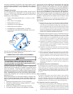
VENT/FLUE AND COMBUSTION AIR PIPE TERMINATIONS
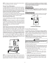
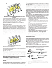
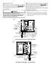
The vent/flue and combustion air pipes may terminate vertically, as
through a roof, or horizontally, as through an outside wall.
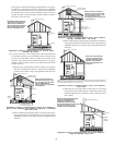
Vertical pipe terminations should be as shown in the following
figure. Refer to Section IX, Vent/Flue Pipe and Combustion Pipe -
Termination Locations for details concerning location restrictions.
The penetrations through the roof must be sealed tight with proper
flashing such as is used with a plastic plumbing vent.
12" MIN.
12" MIN.
TO ROOF OR
HIGHEST
ANTICIPATED
SNOW LEVEL
VENT/FLUE
COMBUSTION
AIR INTAKE
Vertical Terminations (Dual Pipe)
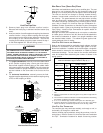
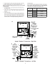
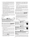
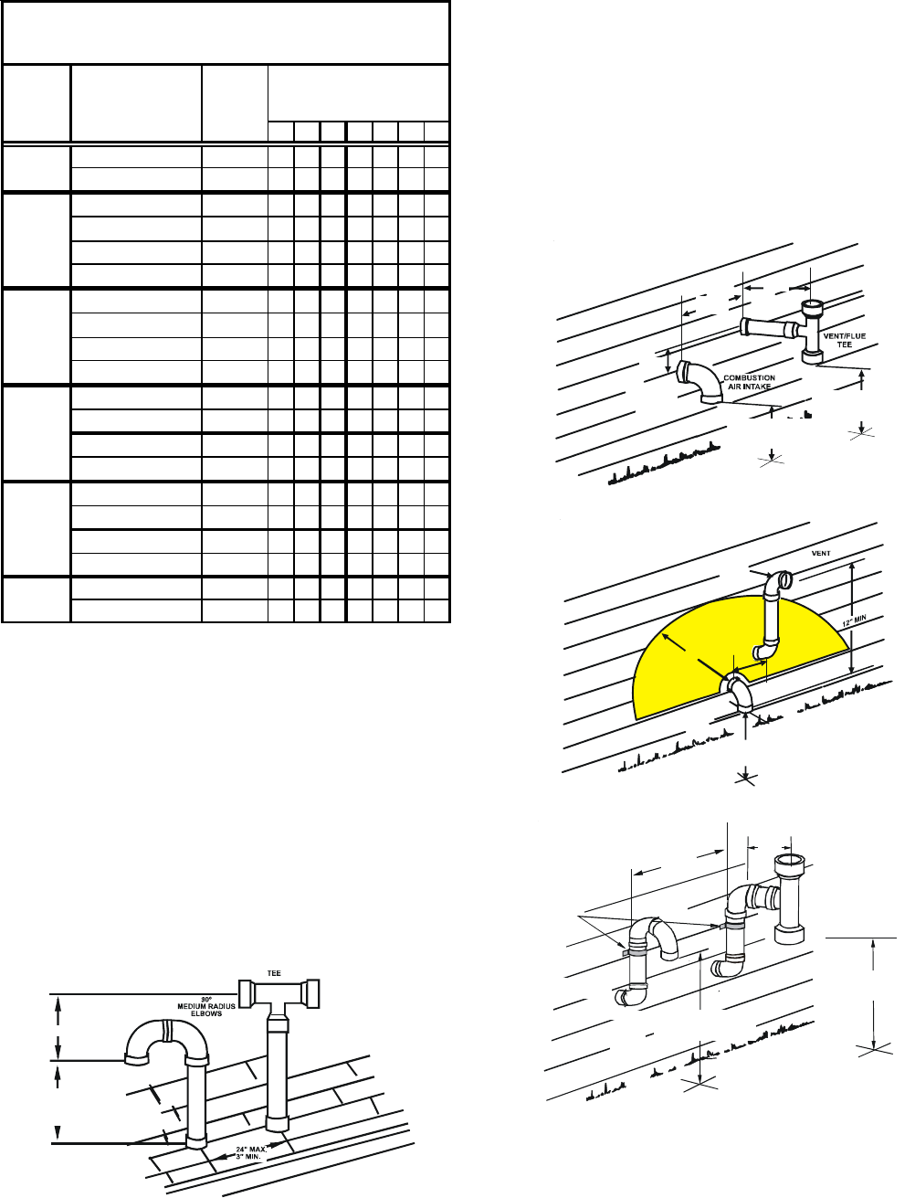
Horizontal terminations should be as shown in the following fig-
ure. Refer to Section IX, Vent/Flue Pipe and Combustion Pipe -
Termination Location for location restrictions. A 2 3/8” diameter
wall penetration is required for 2” diameter pipe. A 3” diameter hole
is required for a 2 1/2” pipe and a 3 1/2” diameter hole is required
for 3” diameter pipe. To secure the pipe passing through the wall
and prohibit damage to piping connections, a coupling should be
installed on either side of the wall and solvent cemented to a pipe
connecting the two couplings. The pipe length should be the wall
thickness plus the depth of the socket fittings to be installed on the
inside and outside of the wall. The wall penetration should be
sealed with silicone caulking material.
90º
MEDIUM RADIUS
ELBOW
12" MIN
3" MIN
24" MAX
3" MIN
24" MAX
12" MIN. ABOVE
HIGHEST ANTICIPATED
SNOW LEVEL
12" MIN. ABOVE
HIGHEST ANTICIPATED
SNOW LEVEL
Standard Horizontal Terminations (Dual Pipe)
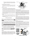
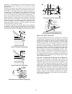
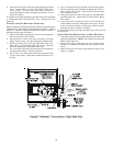
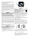
24" MAX
3" MIN
24" MAX
AIR
INTAKE
90°
MEDIUM
RADIUS
ELBOW
12" MIN. ABOVE
HIGHEST ANTICIPATED
SNOW LEVEL
Alternate Horizontal Vent Termination (Dual Pipe)
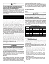
SUPPORT
STRAPS
90°
MEDIUM
RADIUS
ELBOWS
V
ENT/FLUE
TEE
COMBUSTION
AIR INTAKE.
12" MIN. ABOVE
HIGHEST ANTICIPATED
SNOW LEVEL
12" MIN. ABOVE
HIGHEST ANTICIPATED
SNOW LEVEL
3" MIN.
24" MAX.
12" MIN
Standard Horizontal Terminations Above Anticipated Snow
Level (Dual Pipe)