


33
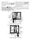
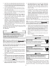
To remove filters from an external filter rack in an upright upflow
installation, follow the directions provided with external filter rack
kit. For further details, see your distributor.
HORIZONTAL U NIT F ILTER R EMOVAL
Filters in horizontal installations are located in the central return
register or the ductwork near the furnace.
To remove:
1. Turn OFF electrical power to furnace.
2. Remove filter(s) from the central return register or ductwork.
3. Replace filter(s) by reversing the procedure for removal.
4. Turn ON electrical power to furnace.
MEDIA AIR F ILTER OR ELECTRONIC AIR C LEANER R EMOVAL
Follow the manufacturer’s directions for service.
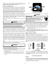
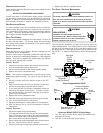
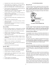
BURNERS
Visually inspect the burner flames periodically during the heating
season. Turn on the furnace at the thermostat and allow several
minutes for flames to stabilize, since any dislodged dust will alter
the flames normal appearance. Flames should be stable, quiet,
soft, and blue (dust may cause orange tips but they must not be
yellow). They should extend directly outward from the burners with-
out curling, floating, or lifting off. Flames must not impinge on the
sides of the heat exchanger firing tubes.
INDUCED D RAFT AND C IRCULATOR B LOWERS
The bearings in the induced draft blower and circulator blower
motors are permanently lubricated by the manufacturer. No further
lubrication is required. Check motor windings for accumulation of
dust which may cause overheating. Clean as necessary.
CONDENSATE TRAP AND DRAIN SYSTEM (QUALIFIED SERVICER
ONLY)
Annually inspect the drain tubes, drain trap, and field-supplied drain
line for proper condensate drainage. Check drain system for hose
connection tightness, blockage, and leaks. Clean or repair as
necessary.
FLAME SENSOR (QUALIFIED SERVICER ONLY)
Under some conditions, the fuel or air supply can create a nearly
invisible coating on the flame sensor. This coating acts as an
insulator causing a drop in the flame sense signal. If the flame
sense signal drops too low the furnace will not sense flame and
will lock out. The flame sensor should be carefully cleaned by a
qualified servicer using emery cloth or steel wool. Following clean-
ing, the flame sense signal should be 1 to 6 microamps.
IGNITER (QUALIFIED SERVICER ONLY)
If the igniter and the surrounding air are at about 70°F and the
igniter wires are not connected to any other electrical components,
the resistance of the igniter should not exceed 200 ohms. If it does,
the igniter should be replaced.
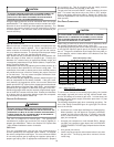
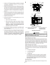
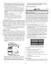
FLUE PASSAGES (QUALIFIED SERVICER ONLY)
The heat exchanger flue passageways should be inspected at the
beginning of each heating season. If necessary, clean the pas-
sageways as outlined below.
1. Turn OFF the electrical power and gas supply to the furnace.
2. Disconnect the gas line and remove the burner/ manifold
assembly by removing the screws securing the assembly
to the partition panel.
3. Disconnect the flue pipe system from the induced draft
blower.
4. Remove the induced draft blower and the drain and pressure
tap hoses from the recuperator coil front cover.
5. Remove the recuperator coil front cover to expose the coil
tubes and turbulators.
6. Remove the recuperator coil turbulators individually by slowly
pulling each turbulator forward firmly.
7. Clean the recuperator coil tubes using a long handle wire
brush, such as a gun cleaning brush.
8. Clean the primary heat exchanger tubes using a wire brush
attached to a length of high grade stainless steel cable,
such as drain cleanout cable. Attach a variable speed
reversible drill to the other end of the cable. Slowly rotate
the cable with the drill and insert it into one of the heat
exchanger tubes. While reversing the drill, work the cable
in and out several times to obtain sufficient cleaning. Repeat
for each tube.
9. Clean residue from furnace using a vacuum cleaner.
10. Replace the parts removed in the previous steps in reverse
order.
11. Turn on electrical power and gas to furnace. Check for
leaks and proper unit operation.
12. Severe heat exchanger fouling is an indication of an
operational problem. Perform the checks listed in Section
XIV, Startup Procedure and Adjustments to reduce the
chances of repeated fouling.
XX. BEFORE LEAVING AN INSTALLATION
• Cycle the furnace with the thermostat at least three times.
Verify cooling and fan only operation.
• Review the Owner’s Manual with the homeowner and
discuss proper furnace operation and maintenance.
• Leave literature packet near furnace.
XXI. REPAIR & REPLACEMENT PARTS
• When ordering any of the listed functional parts, be sure to
provide the furnace model, manufacturing, and serial
numbers with the order.
• Although only functional parts are shown in the parts list, all
sheet metal parts, doors, etc. may be ordered by description.
• Parts are available from your distributor.
Functional Parts List-
Gas Valve Blower Motor
Gas Manifold Blower Wheel
Natural Gas Orifice Blower Mounting Bracket
Propane Gas Orifice Blower Cutoff
Igniter Blower Housing
Flame Sensor Capacitor
Rollout Limit Switch Heat Exchanger
Primary Limit Switch Recuperator Coil
Auxiliary Limit Switch Coil Front Cover
Pressure Switch Integrated Control Module
Induced Draft Blower Transformer
Door Switch