


30
3. Calculate the number of seconds per cubic foot (sec/ft
3
) of
gas being delivered to the furnace. If the dial is a one cubic
foot dial, divide the number of seconds recorded in step 2
by one. If the dial is a two cubic foot dial, divide the number
of seconds recorded in step 2 by two.
4. Calculate the furnace input in BTUs per hour (BTU/hr). Input
equals the installation’s gas heating value multiplied by a
conversion factor (hours to seconds), divided by the number
of seconds per cubic foot. The measured input must not be
greater than the input indicated on the unit rating plate.
EXAMPLE:
Installation’s gas heating (HTG) value: 1,000 BTU/ft
3
(Obtained from gas supplier)
Installation’s seconds per cubic foot: 34 sec/ ft
3
Conversion Factor (hours to seconds): 3600 sec/hr
Input = (Htg. value x 3600) ÷ seconds per cubic foot
Input = (1,000 BTU/ft
3
x 3600 sec/hr) ÷ 34 sec/ ft
3
Input = 106,000 BTU/hr
Minor changes to the input rate may be accomplished through
manifold pressure adjustments at the gas valve. Refer to Section
XIV, Startup Procedure and Adjustment - Gas Manifold Pressure
Measurement and Adjustment for details. NOTE: The final mani-
fold pressure cannot vary by more than ± 0.3” w.c. from the speci-
fied setting. Consult your local gas supplier if additional input rate
adjustment is required.
5. Turn ON gas to and relight all other appliances turned off in
step 1. Be certain that all appliances are functioning properly
and that all pilot burners are operating.
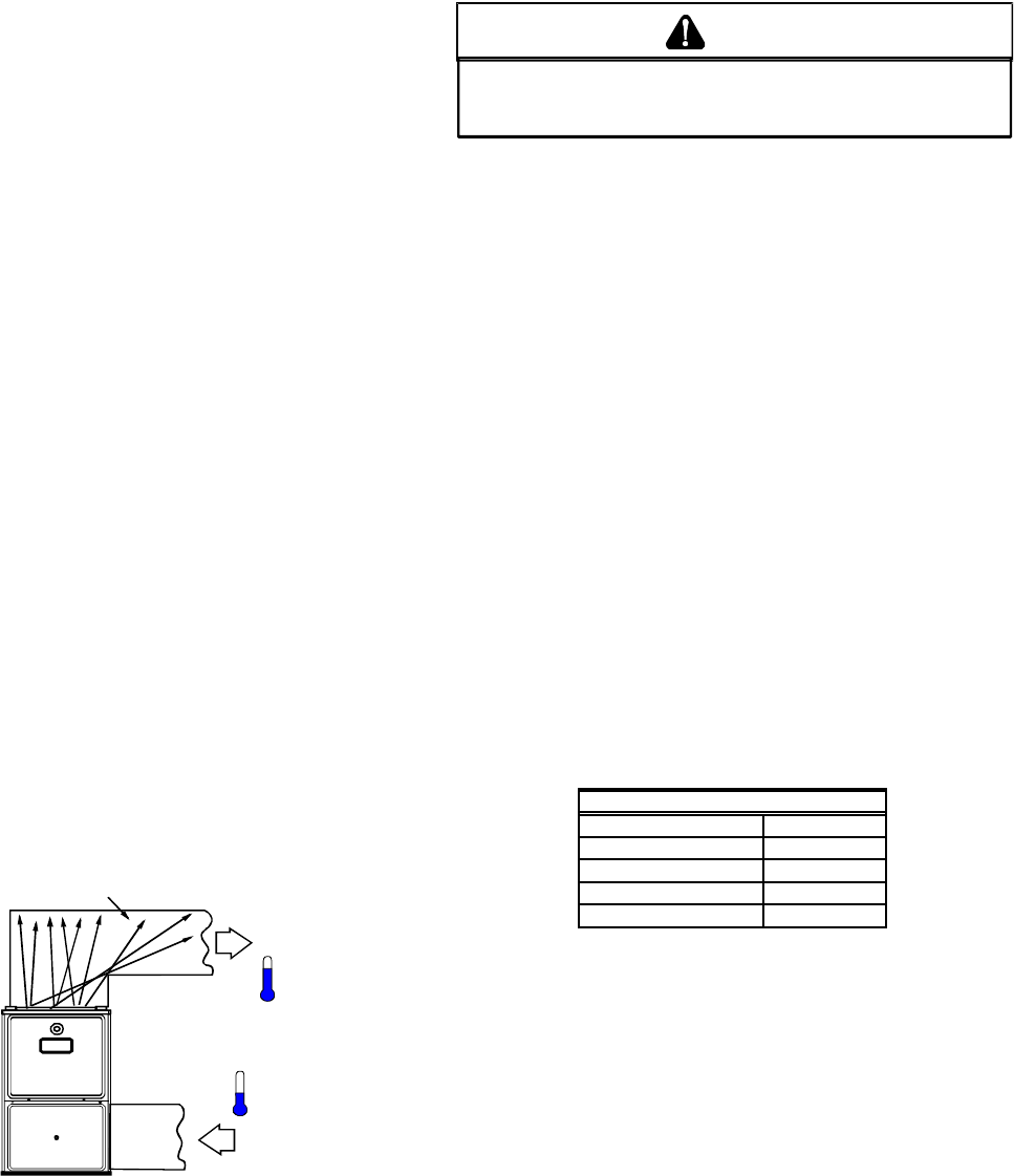
TEMPERATURE RISE
Temperature rise must be within the range specified on the unit
rating plate. An incorrect temperature rise may result in condens-
ing in or overheating of the heat exchanger. An airflow and tem-
perature rise table is provided in the Specification Sheet applicable
to your model. Determine and adjust temperature rise as follows:
1. Operate furnace with burners firing for approximately ten
minutes. Ensure all registers are open and all duct
dampers are in their final (fully or partially open) position.
2. Place thermometers in the return and supply ducts as close
to the furnace as possible. Thermometers must not be
influenced by radiant heat by being able to “see” the heat
exchanger.
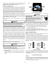
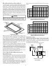
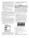
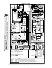
RISE =
SUPPLY
AIR
RETURN
AIR
HEAT EXCHANGER
RADIATION "LINE OF SIGHT"
T
RETURN
T
SUPPLY
T
SUPPLY
-
T
RETURN
Temperature Rise Measurement
3. Subtract the return air temperature from the supply air
temperature to determine the air temperature rise. Allow
adequate time for thermometer readings to stabilize.
4. Adjust temperature rise by adjusting the circulator blower
speed. Increase blower speed to reduce temperature rise.
Decrease blower speed to increase temperature rise. Refer
to Section XIV, Startup Procedure and Adjustment -Circulator
Blower Speeds for speed changing details.
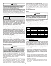
CIRCULATOR B LOWER S PEEDS
T
O
PREVENT
PREMATURE
FAILURE
OF
HEAT
EXCHANGER
,
PROPERTY
DAMAGE
,
PERSONAL
INJURY
OR
DEATH
,
DO
NOT
ADJUST
THE
LIMIT
CONTROL
(
FACTORY
-
SET
).
WARNING
This furnace is equipped with a multi-speed circulator blower. This
blower provides ease in adjusting blower speeds. The Specifica-
tion Sheet applicable to your model provides an airflow table, show-
ing the relationship between airflow (CFM) and external static pres-
sure (E.S.P.), for the proper selection of heating and cooling speeds.
The cooling blower speed is shipped set on HIGH, and the heating
blower speed is set as indicated in the Specification Sheet appli-
cable to your model. These blower speeds should be adjusted by
the installer to match the installation requirements so as to provide
the correct heating temperature rise and correct cooling CFM.
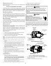
To adjust the circulator blower speed, proceed as follows:
1. Turn OFF power to the furnace.
2. Select the heating and cooling blower speeds that match
the installation requirements from the airflow table in the
Specification Sheet.
3. Relocate desired motor leads to the circulator blower heat
and cool speed terminals on the integrated control module.
(Terminals are identified as HEAT and COOL (hot)). If heating
and cooling blower speeds are the same, a jumper wire
must be used between the heat and cool terminals.
4. Connect all unused blower motor leads to the “PARK”
terminals on the integrated control module. Any leads not
connected to the “PARK” terminals must be taped.
5. Turn ON power to furnace.
6. Verify proper temperature rise as outlined in Section XIV,
Startup Procedure and Adjustment - Temperature Rise.
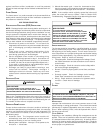
Oran
g
e
Hi
g
h
Common/Neutral
Medium Low
Circulator Blower S
p
eeds
Low Red
Medium Blue
Black
White
XV. NORMAL SEQUENCE OF OPERATION
POWER UP
The normal power up sequence is as follows:
• 115 VAC power applied to furnace.
• Integrated control module performs internal checks.
• Integrated control module LED will light.
• Integrated control module monitors safety circuits
continuously.
• Furnace awaits call from thermostat.
HEATING MODE
The normal operational sequence in heating mode is as follows:
• R and W thermostat contacts close, initiating a call for heat.