


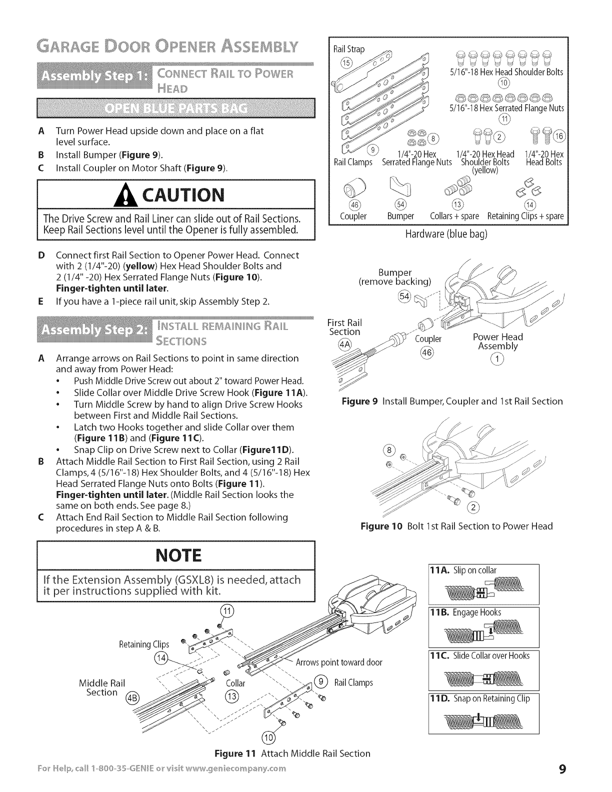
COIl CT RAIL TO I ©WEF_
A
B
C
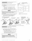
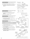
Turn Power Head upside down and place on a flat
level surface.
Install Bumper (Figure 9).
Install Coupler on Motor Shaft (Figure 9).
CAUTION
The Drive Screw and Rail Liner can slide out of Rail Sections.
Keep Rail Sections level until the Opener is fully assembled.
D Connect first Rail Section to Opener Power Head. Connect
with 2 (1/4"-20) (yellow) Hex Head Shoulder Bolts and
2 (1/4"-20) Hex Serrated Flange Nuts (Figure 10).
Finger-tighten until later.
E If you have a 1-piece rail unit, skip Assembly Step 2.
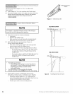
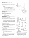
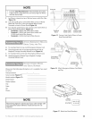
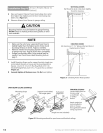
A Arrange arrows on Rail Sections to point in same direction
and away from Power Head:
• Push Middle Drive Screw out about 2" toward Power Head,
• Slide Collar over Middle Drive Screw Hook (Figure 11A).
• Turn Middle Screw by hand to align Drive Screw Hooks
between First and Middle Rail Sections.
• Latch two Hooks together and slide Collar over them
(Figure 11B) and (Figure 11C).
• Snap Clip on Drive Screw next to Collar (Figure11D).
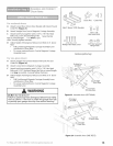
B Attach Middle Rail Section to First Rail Section, using 2 Rail
Clamps, 4 (5/16"-18) Hex Shoulder Bolts, and 4 (5/16"-18) Hex
Head Serrated Flange Nuts onto Bolts (Figure 11).
Finger-tighten until later. (Middle Rail Section looks the
same on both ends. See page 8.)
C Attach End Rail Section to Middle Rail Section following
procedures in step A & B.
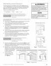
RailStrap
RailClamps
@
Coupler
1/4"-20 Hex
SerratedFlangeNuts
%
@
Bumper
S/16"-18HexHeadShoulderBolts
@
5/16"-18HexSerratedFlangeNuts
@
1/4"-20HexHead 1/4"-20Hex
ShoulderBolts HeadBolts
(yellow)
@ @
Collars+ spare Retaining Clips+ spare
Hardware (blue bag)
Bumper
(remove backing)
@ Jfi
First Rail
Section
Coupler Power Head
Assembly
Figure 9 Install Bumper, Coupler and 1st Rail Section
Figure 10 Bolt 1st Rail Section to Power Head
11A. Slipon collar
1B. EngageHooks
11 C._Slide Collarover Hooks
11 D._Snap on Retaining Clip
9