


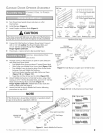
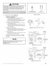
CAUTION
;taples which are too tight may cut or pinch Wires. Cut or
)inched Wires can cause the Safe-T-Beam® System to stop
working. When installing the Insulated Staples, make sure
_oufasten them only as tightly as needed to hold the
Wire securely.
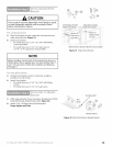
®
Insulated Staples
(approximately 30 parts)
©
#6-11/4"
Pan Head Screws
C
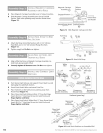
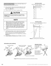
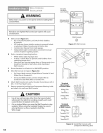
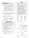
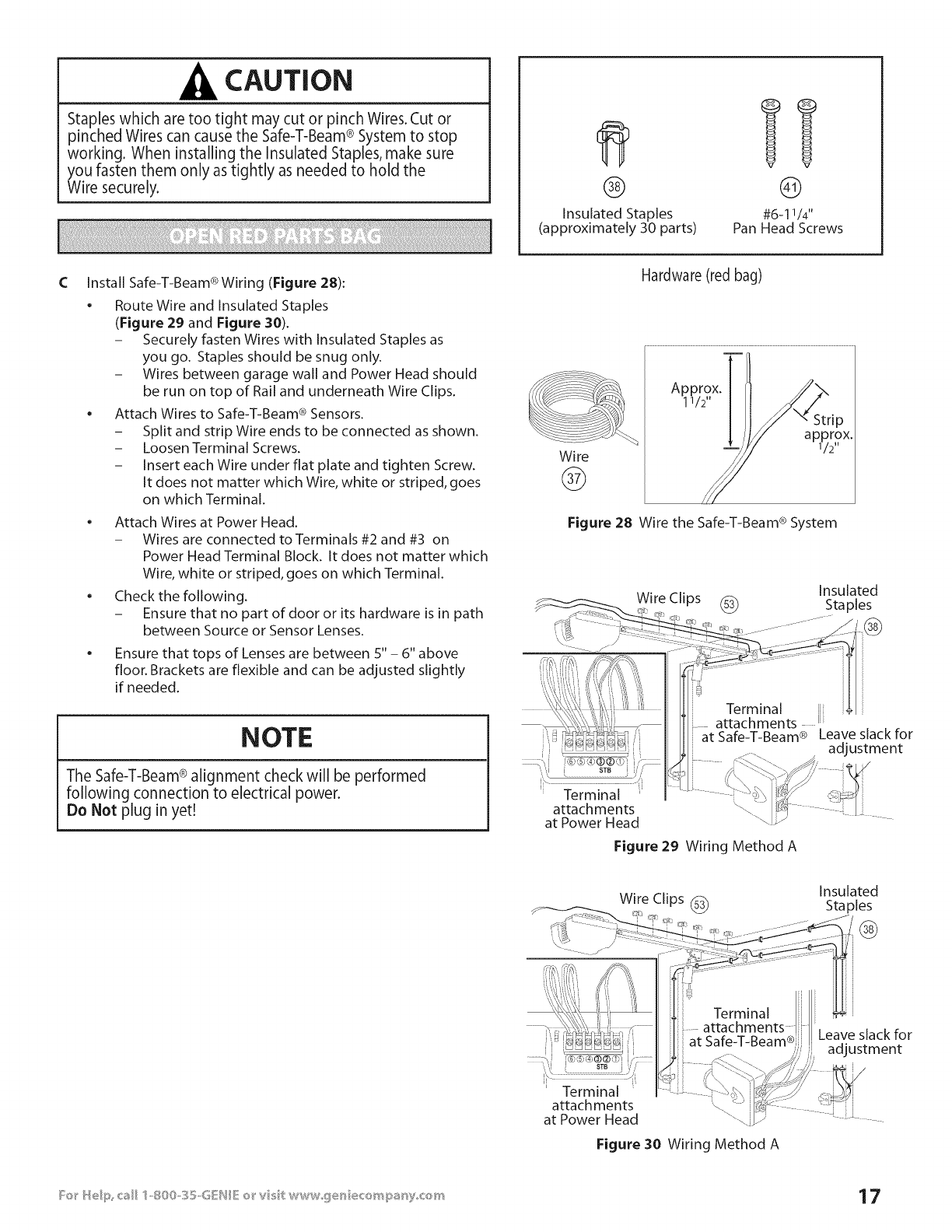
Install Safe-T-Beam ®Wiring (Figure 28):
• Route Wire and Insulated Staples
(Figure 29 and Figure 30).
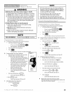
- Securely fasten Wires with Insulated Staples as
you go. Staples should be snug only.
- Wires between garage wall and Power Head should
be run on top of Rail and underneath Wire Clips.
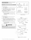
Attach Wires to Safe-T-Beam ®Sensors.
- Split and strip Wire ends to be connected as shown.
- Loosen Terminal Screws.
- Insert each Wire under flat plate and tighten Screw.
It does not matter which Wire, white or striped, goes
on which Terminal.
• Attach Wires at Power Head.
- Wires are connected to Terminals #2 and #3 on
Power Head Terminal Block. It does not matter which
Wire, white or striped, goes on which Terminal.
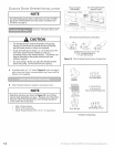
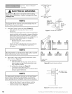
Check the following.
- Ensure that no part of door or its hardware is in path
between Source or Sensor Lenses.
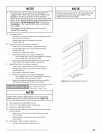
• Ensure that tops of Lenses are between S" - 6" above
floor. Brackets are flexible and can be adjusted slightly
if needed.
Wire
@
Hardware (red bag)
Approxi112
X,
Figure 28 Wire the Safe-T-Beam ® System
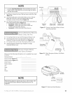
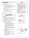
NOTE
The Safe-T-Beam®alignment check will be performed
following connection to electrical power.
Do Not plug in yet!
at Safe-T-Beam ®
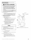
Figure 29 Wiring Method A
Leave slack for
adjustment
Wire Clips (_
Insulated
Staples
@
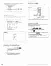
STB j
i
Terminal
attach ments
at Power Head
at Safe-T-Beam® J
Figure 30 Wiring Method A
Leave slack for
adjustment