


Co_s_scs__sG_ovv_
ELECTRICALWARNING
e
A
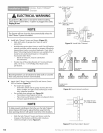
To reduce the risk of electrical shock, this equipment has
a grounding type Plug that has a third (grounding) Pin.
This Plug will only fit into a grounding type outlet. If the
Plug does not fit into the outlet, contact a qualified
electrician to install the proper outlet. Do Not change
the Plug in any way.The door Opener must be properly
grounded to prevent personal injury and damage to the
components.
The electrical power to the door Opener Must Be removed
when the Motor Cover is removed. Electrical power must
remain off while making electrical connections.
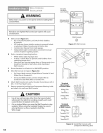
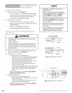
Check building codes:
• If building code requires Opener be permanently wired
to building, have a licensed electrician perform step B.
• If you are not installing permanent wiring, go to step C.
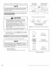
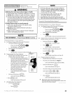
Instructions for licensed electrician - connecting power
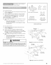
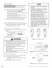
with permanent wiring (Figure 33):
• Remove power from circuit.
• Remove Motor Cover.
• Remove and discard Power Cord.
- Cut off Power Cord inside Power Head as near Strain
Relief as possible.
- Remove Knock-Out Plug, Strain Relief, and Power
Cord. (Cut Ground Wire on line side of Toroid).
- Dispose of Plug, Strain Relief, and Power Cord.
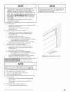
• Install required entrance bushing.
• Connect permanent wiring to Power Head Wires.
- White supply line to Opener White Wire.
- Black supply line to Opener Black Wire.
- Ground to Opener Green Wire.
- Replace Motor Cover.
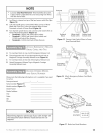
NOTE
e
Use only Underwriters Laboratories, Inc. (U.L.)
recognized wire nuts.
The Circuit Boards are light sensitive. Ensure the
Motor Cover is installed before energizing
the Opener.
Knockout
Cut
Wires
here
Two
tabs
slide
out
I
Four screws hold
Motor Cover
Figure 33 Connecting power with permanent wiring
C
D
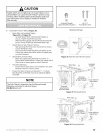
- Restore Power to circuit.
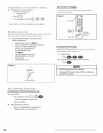
Connecting Power with Plug:
• Plug Opener into a grounded outlet as stated in previous
electrical warning.
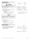
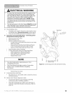
Perform Safe-T-Beam ®alignment check:
• Check if Safe-T-Beam ® Source Red LED is glowing
continuously (OK) or blinking (problem).
• If Red LED is blinking twice, adjust Sensor Brackets as
needed to make Red LED glow continuously. (Refer to
page 26.)