


A
B
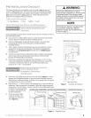
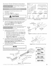
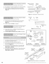
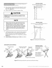
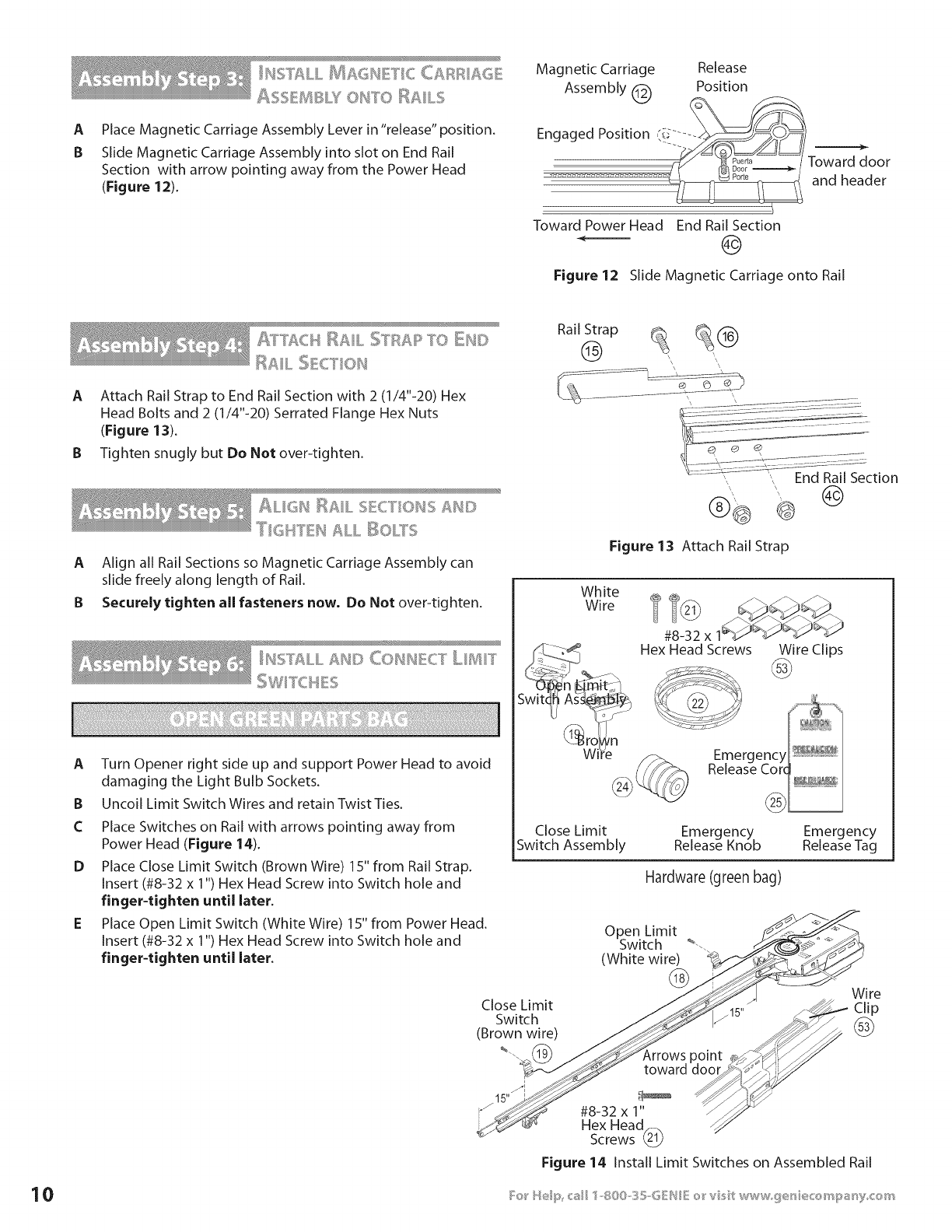
Place Magnetic Carriage Assembly Lever in "release" position.
Slide Magnetic Carriage Assembly into slot on End Rail
Section with arrow pointing away from the Power Head
(Figure 12).
Magnetic Carriage Release
Assembly _ Position
kCC/
Engaged Position (i_.... -__/_/
To.o=
.................................. _ andheader
Toward Power Head End Rail Section
Figure 12 Slide Magnetic Carriage onto Rail
A]_]'ACH RAIL STRAR TO DU©
RAIL :_E_._[l,N
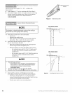
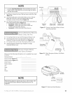
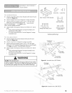
A Attach Rail Strap to End Rail Section with 2 (1/4"-20) Hex
Head Bolts and 2 (1/4"-20) Serrated Flange Hex Nuts
(Figure 13).
B Tighten snugly but Do Not over-tighten.
Rail Strap _@
'I? I & I "
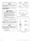
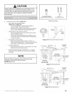
ALIGH I_AIL SECTIONS ;_N©
A Align all Rail Sections so Magnetic Carriage Assembly can
slide freely along length of Rail.
B Securely tighten all fasteners now, Do Not over-tighten.
I¢2 = =_'_ & I "=S,>%, LL _S[} CONNECT LIIIIT
A
B
C
D
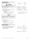
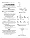
Turn Opener right side up and support Power Head to avoid
damaging the Light Bulb Sockets.
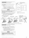
Uncoil Limit Switch Wires and retain Twist Ties.
Place Switches on Rail with arrows pointing away from
Power Head (Figure 14).
Place Close Limit Switch (Brown Wire) 15" from Rail Strap.
Insert (#8-32 x 1") Hex Head Screw into Switch hole and
finger-tighten until later.
Place Open Limit Switch (White Wire) 15" from Power Head.
Insert (#8-32 x 1") Hex Head Screw into Switch hole and
finger-tighten until later.
Figure 13 Attach Rail Strap
White
Wire
#8-32 x
Hex Head Screws
Wire Clips
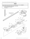
Close Limit Emergency Emergency
Switch Assembly Release Knob Release Tag
Hardware (green bag)
Close Limit
Switch
(Brown wire)
%.
i
15"
Open Limit
Switch _--.
(White wire)
@
Wire
_15" j_- Clip
,rro..t
toward I_o_#i_
#8-32 x 1" --_"_
Hex Head_
Screws
Figure 14 Install Limit Switches on Assembled Rail