


WF_LL C©BSS©L
WARNING
Verify there is no power to the Opener before installing Wall
Console Wires.
NOTE
More than one lighted Wall Control per Opener will cause
a malfunction.
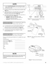
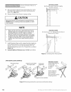
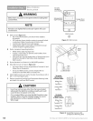
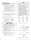
A Wall Console (Figure 31):
• Has a Security Vacation Lock Switch which disables
all controls.
• LED Indicator shows whether system is powered, locked,
or unlocked. Makes Console easy to find in dark.
• Controls door Opener from inside garage.
• Independent Light Control allows convenient manual
control of Opener Lighting System.
B Find a convenient mounting location:
• Within direct sight of garage door.
• At least 5' above floor (to prevent small children from
operating garage door).
• Away from any moving garage door or Opener parts (you
should not be able to reach door while standing at
Wall Console).
C Ensure Vacation Lock Switch is in UNLOCKED position.
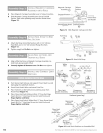
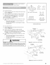
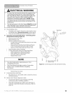
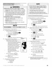
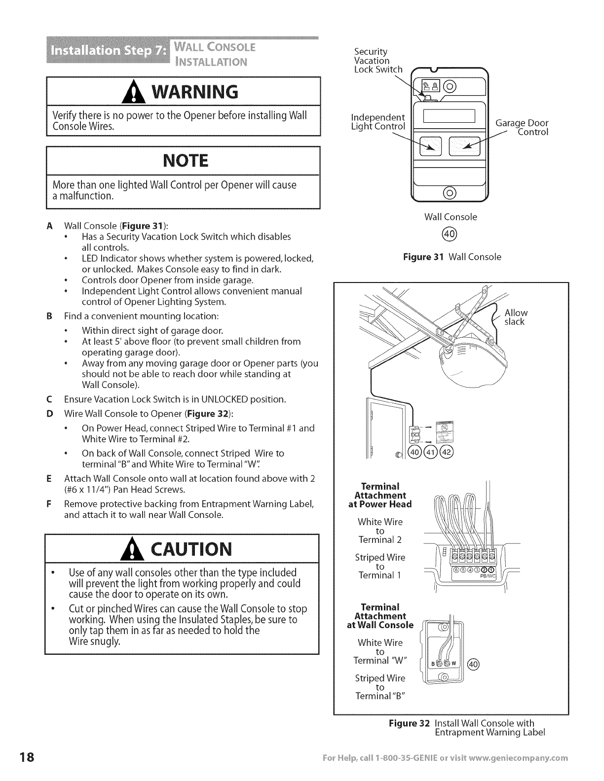
D Wire Wall Console to Opener (Figure 32):
• On Power Head, connect Striped Wire to Terminal #1 and
White Wire to Terminal #2.
• On back of Wall Console, connect Striped Wire to
terminal "B" and White Wire to Terminal "W'[
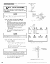
E Attach Wall Console onto wall at location found above with 2
(#6 x 11/4") Pan Head Screws.
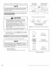
F Remove protective backing from Entrapment Warning Label,
and attach it to wall near Wall Console.
CAUTION
e
Use of any wall consoles other than the type included
will prevent the light from working properly and could
cause the door to operate on its own.
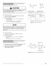
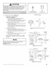
Cut or pinched Wires can cause the Wall Console to stop
working. When using the Insulated Staples, be sure to
only tap them in as far as needed to hold the
Wire snugly.
Security
Vacation
Lock Switch
Independent
Light Control
1
[ I
Garage Door
J Control
©
Wall Console
@
Figure 31 Wall Console
Allow
slack
®®@
Terminal
Attachment
at Power Head
White Wire
to
Terminal 2
Striped Wire
to
Terminal 1
Terminal
Attachment
at Wall Console
White Wire
to
Terminal "W"
Striped Wire
to
Terminal "B"
®
Figure 32 Install Wall Console with
Entrapment Warning Label