


9
l. Inspect Beckett head setting on left side of
burner by insuring the blue line MD(V1) or the
line on the label MB(L1) are aligned, readjust if
necessary.
m. Tighten knurled nut.
n. Swing igniter closed, rotate tabs and tighten two
(2) igniter screws.
o. Replace burner cover and tighten burner cover
knobs.
3. On the Carlin EZ-PH Burner, use the following
procedure to complete the inspection, check the
settings and to change the nozzle to a lower ring
rate:
a. Loosen two (2) igniter latching screws, rotate
tabs and swing open igniter about hinge.
b. Loosen knurled nut and disconnect copper
connector tube.
c. Remove nozzle line electrode assembly from
burner.
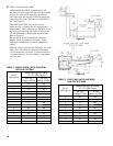
d.
If high ring rate is desired, conrm the nozzle
is the proper size and type, refer to Table 9, then
proceed to Item i. below.
e. If a lower input is desired, remove the ame
retention head and then remove the nozzle that
was factory installed.
f.
Locate the desired nozzle, refer to Table 9 for
proper nozzle. The nozzle must be securely
installed to assure leak free joints between the
nozzle and adapter. When installing the nozzle,
be careful not to bump or move the burner
electrodes.
g.
Reinstall Flame Retention Head on Nozzle Line
Electrode Assembly. Make sure the clamp is
fully sated against the shoulder on the nozzle
adapter before securing.
h. Loosen and remove the retaining nut and factory
installed head bar from side of burner housing.
Install the proper head bar that corresponds
to the desired ring rate, refer to Table 9, and
tighten retaining nut.
i. Readjust air band to preliminary setting that
corresponds to the lower ring rate nozzle
installed, refer to Table 9.
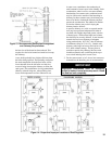
j. Inspect and measure burner electrodes. Refer
to Figure 25A for proper electrode setting.
Readjust electrode setting to the proper
dimensions if necessary.
k. Reinstall nozzle line electrode assembly.
l. Reconnect copper connector tube.
m. Tighten knurled nut.
n. Close igniter, rotate and tighten two (2) igniter
latching screws.
4.
On the Riello 40 Series Oil Burner, use the
following procedure to complete the inspection,
check the settings and to change the nozzle to a
lower ring rate:
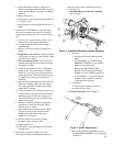
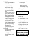
a. Installation/Removal of Drawer Assembly,
refer to Figure 4.
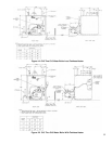
Figure 4: Installation/Removal of Drawer Assembly
i. Removal:
• Disconnect oil delivery tube nut from
pump.
• Loosen SCREW (3), and then unplug
PRIMARY CONTROL (1) by carefully
pulling it back and then up.
• Remove the AIR TUBE COVER
PLATE (5) by loosening the retaining
SCREW (4) (Two SCREWS-Model F5).
• Loosen SCREW (2), and then slide the
complete drawer assembly out of the
combustion head as shown.
ii. Installation:
To insert drawer assembly, reverse the
procedure in Step i above.
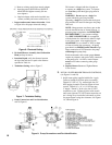
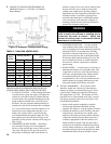
b. Nozzle Replacement, refer to Figure 5.
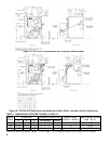
Figure 5: Nozzle Replacement
i. Remove the NOZZLE ADAPTER (2) from
the DRAWER ASSEMBLY by loosening the
SCREW (1).