


26
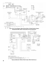
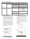
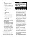
Figure 24: Setpoints and Differentials
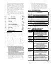
System Condition Diagnostic Condition Check Action
Boiler is cold, house is
cold.
Display is OFF. 120 Vac System power. Turn system power on.
Display is ON. 24 Vac T-T No 24 V; replace control.
24 V present; disconnect
thermostat, short T-T.
Boiler starts, check wiring and thermostat.
120 Vac at B1-B2 • If no, replace control.
• If yes, check burner and wiring.
Refer to Err on display. -----
Boiler is hot, house is
cold.
Display is ON. 120 Vac at C1-C2 • 120 Vac at C1-C2, check wiring
to pump.
• Wiring OK, is pump running?
• If not, replace the pump.
• If pump is running, check for
trapped air or closed zone valves
Boiler below the Low Limit
temperature, wait for boiler to go
above Low Limit temperature.
-----
Boiler above LL? If yes, check
for 120 Vac between ZC and L2.
• If no 120 Vac , replace control.
• If yes, check zone relays, circulators
and wiring.
TABLE 8: TROUBLE SHOOTING GUIDE
7. HIGH LIMIT CONTROLLER
The High Limit opens and turns off the burner
when the water temperature reaches the setpoint.
The High Limit automatically resets after the water
temperature drops past the setpoint and through the
Differential. The L7248 models have High Limit
Differential presets of 15°F (8°C). The L7224
models have High Limit Differential presets of 10°F
(6°C).
8.
LOW LIMIT AND CIRCULATOR CONTROLLER
On a temperature rise, with the adjustable
Differential at the default setting of 10°F (6°C),
the burner circuit breaks and the circulator circuit
makes (assuming no call for heat is present) at the
Low Limit setpoint. On a temperature drop of 10°F
(6°C) below the Low Limit setpoint, the burner
circuit makes and the circulator circuit breaks. See
Figure 24.
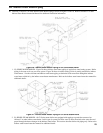
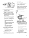
F. REMOVE GUN ASSEMBLY
1. CL Series boilers are equipped with Beckett AFG
burners. Items to be checked are nozzle size, head
size, gun setting, and positioning of electrodes. This
information is shown in Figure 25 and Table 9 at
rear of manual.
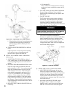
2. CL Series boilers are equipped with Carlin EZ-HP
burners. Items to be checked are nozzle size, head
bar size, gun setting, and positioning of electrodes.
This information is shown in Figure 25A and Table
9 at rear of manual.
3. Reinstall gun assembly.
Figure 25: "L1" and "V1" Head Electrode
Positioning and Gun Setting (Beckett AFG)