


25
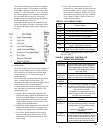
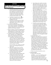
Figure 23: Display Readout Denitions
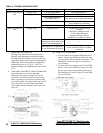
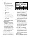
TABLE 7: L7248/L7224 CONTROLLER
OPERATING SEQUENCE
TABLE 6: LED ERROR CODES
Error
Code
Cause / Action
Err1 Sensor fault; check sensor.
Err2 ECOM fault; check EnviraCOM™ wiring.
Err3 Hardware fault; replace control.
Err4 B1 fault; check B1 wiring/voltage.
Err5 Low Line; check L1-L2, 110 Vac.
Err6 Fuse; check ECOM wires, replace fuse.
Err7
EEPROM, HL, LL, Hdf, Ldf; reset to default
values. Restore desired settings.
Err8
Repeated B1 fault (voltage present at B1 when
output is turned off); check B1 wiring/voltage.
6. OPERATION
The L7224 model can be in any of four operational
states - Normal, High Limit, Low Limit and Error.
The controller moves back and forth from High
Limit to Normal to Low Limit state as part of
normal operation.
The L7248 model is restricted to three operational
states - Normal, High Limit and Error. The
controller moves back and forth from High Limit to
Normal state as part of normal operation.
For both models, the controller will enter the Error
state when there is an abnormal condition. The
operating states are:
a. Normal: Boiler temperature went below the
High Limit setting (minus the Differential) and
has not exceeded the High Limit setting; or the
boiler temperature went above the Low Limit
setting and has not gone below the Low Limit
setting (minus the Differential).
b. High Limit: Boiler temperature went above the
High Limit setting and has not dropped below
the High Limit setting (minus the Differential).
c. Low Limit: Boiler temperature went below
the Low Limit setting (minus the Low Limit
Differential) and has not gone above the Low
Limit setting.
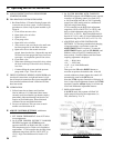
To read boiler settings, press the I key to read the
parameter of interest. For example, press I High
Limit (HL) is displayed, followed by a three-digit
number, i.e., 220, followed by °F or °C. Pressing
the I button again (on L7224 models) will display
the Low Limit (LL) followed by a three-digit
number and the corresponding degree designator.
See Display Readout, Figure 23.
After approximately 60 seconds without any key
presses, the display will enter a dim display mode.
To return to the bright display mode, simply press
any key.
d. Error: The controller has detected an error
condition (e.g., open sensor) and has shut down
the burner output. The ZC output is energized.
The controller continues to monitor the system
and automatically restarts if the error condition
clears. Refer to Table 6. Refer to Table 8 for
Trouble Shooting Guide.
Action System Response
Thermostat
calls for heat.
Circulator starts when water temperature
is above Low Limit setting (if applicable).
Boiler temperature is checked. Burner
starts when water temperature is below
High Limit setting.
Boiler
exceeds the
High Limit.
Burner is turned off. Burner restarts when
the water temperature drops below the
High Limit setting minus the Differential.
Thermostat is
satised.
Circulator and burner turn off.
Error
condition 1-5.
If an error condition is detected, all outputs
except ZC are shut down. Burner is off.
Control continues to function and restarts
when error is corrected.
During the error check sequence, the
system checks for drift in the sensor and
corrosion in the connections.
Error
condition 6.
EnviraCOM communication is not
available.
Error
condition 7.
The control has reset the High Limit, Low
Limit and Differential setting to a default
setting and will continue to run at those
settings.
Performance of the system will be
degraded.
Error
condition 8.
If the error condition is detected, all
outputs except ZC are shut down. Burner
is off. Control continues to function and
restarts when all three user keys have
been pressed longer than 60 seconds.
The operating sequence for the L7224/L7248 is
shown in Table 7.