


8
II. Installation Instructions
A. REMOVE CRATE
1. Remove all fasteners at crate skid.
2. Lift outside container and remove all other
inside protective spacers and bracing. Remove
miscellaneous steam or water trim carton.
3.
Using hand truck or pipe rollers under skid, move
boiler into position along side installation site.
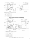
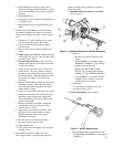
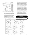
B. REMOVAL OF BOILER FROM SKID
1. Boiler is secured to base with 4 carriage bolts, 2 on
left side and 2 on right side. See Figure 3. Remove
all bolts.
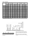
1. PACKAGED CL™ Series boilers are shipped with
the highest input oil nozzle installed in the burner.
Oil nozzles for lower ring rates are shipped
loose for the CL3 through CL5 models, attached
to the burner. Select the proper oil nozzle for the
installation. The lower input nozzle will provide
greater boiler efciency. However, boiler output
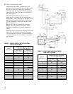
will be reduced. Refer to Table 2 for ring rates.
If the higher rate is desired, inspect the installed
nozzle and assure that the nozzle is the correct size
and type as specied in Tables 9 and 9A of this
manual.
If a lower input is desired, remove the nozzle
which was factory installed. Locate the lower ring
rate nozzle that is supplied loose. Conrm the
nozzle is the proper size and type for the lower ring
rate as specied in Tables 9 and 9A of this manual.
Install the proper nozzle in the burner nozzle
adaptor.
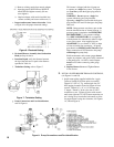
2.
On the Beckett AFG Burner, use the following
procedure to complete the inspection, check the settings
and to change the nozzle to a lower ring rate:
a. Loosen two (2) igniter latching screws, rotate
tabs and swing open igniter about hinge.
b.
Loosen knurled nut and disconnect copper
connector tube.
c. Remove nozzle line electrode assembly.
d. If high ring rate is desired, conrm the nozzle
is the proper size and type, refer to Table 9, then
proceed to Item i. below.
e.
If a lower input is desired, remove the nozzle
that was factory installed.
f. Remove Beckett MD(V1) or MB(L1) head.
g. Locate the desired nozzle. Refer to Table 9 for
proper nozzle. The nozzle must be securely
installed to assure leak free joints between the
nozzle and adapter. When installing the nozzle,
be careful not to bump or move the burner
electrodes.
NOTE: On the CL3-091 (0.65 GPH) burner
application, a low ring rate bafe is required.
Bafe is shipped loose with nozzles. Install
bafe per Beckett Instruction included with
bafe.
h. Reinstall Beckett MD(V1) or MB(L1) Head.
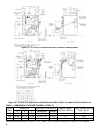
i. Inspect and measure burner electrodes. Refer
to Figure 25 for the proper electrode setting.
Readjust electrode setting to the proper
dimensions if necessary. Refer to Figure 25.
j. Reinstall nozzle line electrode assembly.
k. Connect copper connector tube.
2. Tilt boiler to right and to rear. Using right rear leg
as pivot, rotate boiler 90° in a clockwise direction,
and lower left side of boiler to oor. Tilt boiler
and remove crate skid. Care should be exercised to
prevent damage to jacket or burner.
C. MOVE BOILER TO PERMANENT POSITION by
sliding or walking.
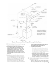
D. INSPECT COMBUSTION TARGET WALL AND
COMBUSTION CHAMBER LINER
1. OPEN FLAME OBSERVATION DOOR AND/
OR BURNER SWING DOOR on front of boiler.
Use ashlight to inspect target wall secured to
rear section with silastic sealant. Inspect ceramic
ber blanket secured to oor of boiler with water
glass adhesive. If either is damaged they must be
replaced.
E. INSPECT NOZZLE, ELECTRODES INSERTION
DEPTH AND TURBULATOR SETTING/CHANGE
FIRING RATE: Refer also to Model F3 & F5
Installation Manual, Riello 40 Series Residential Oil
Burners (C6501010) or Model F10 Installation Manual,
Riello 40 Series Residential Oil Burners (2902554).
Figure 3: Removal of Boiler From Skid