


10
ii. Remove existing nozzle from nozzle adapter.
iii.
Insert the proper NOZZLE into NOZZLE
ADAPTER and tighten securely (Do not
cover tighten).
iv. Replace adapter, with nozzle installed, into
drawer assembly and secure with screw (1).
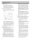
c.
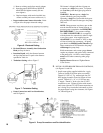
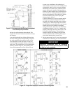
Inspect and measure burner electrodes. Refer
to Figure 6 for the proper electrode settings.
Figure 6: Electrode Setting
d. Re-install Drawer
Assembly into Combustion
Head per Step 4a above.
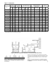
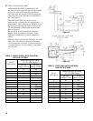
e. Insertion Depth, verify the distance between
the tip of the end cone is equal to the distance
specied in Table 9A.
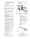
f. Turbulator Setting, refer to Figure 7.
Figure 7: Turbulator Setting
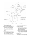
g. Pump Connections and Port Identication,
refer to Figure 8.
Figure 8: Pump Connections and Port Identication
This burner is shipped with the oil pump set
to operate on a single line system. To operate
on a two-line system the bypass plug must be
installed.
WARNING: Do not operate a single line
system with the by-pass plug installed.
Operating a single line system with the by-pass
plug installed will result in damage to the pump
shaft seal.
NOTE: Pump pressure was factory pre-set but
must be checked at time of burner start-up. A
pressure gauge is attached to the PRESSURE/
BLEEDER PORT (7) for pressure readings.
Two PIPE CONNECTORS (4) are supplied
with the burner for connection to either a single
or two-line system. Also supplied are two
ADAPTORS (3), two female ¼” NPT to adapt
oil lines to burner pipe connectors. All pump
port threads are British Parallel Thread design.
Direct connection of NPT threads to the pump
will damage the pump body.
Riello manometers and vacuum gauges do not
require any adapters, and can be safely connected
to the pump ports. An NPT x metric adapter
must be used when connecting other gauge
models.
h. Replace Burner Cover and Tighten Burner
Cover Screws.
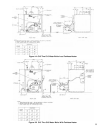
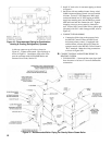
F. INSTALL WATER BOILER TRIM AND CONTROLS,
(see Figures 1A and 1B)
1. Install return piping supplied with boiler. Apply
Teon or Sealant to all joints prior to assembly.
Thread 1½" NPT x 5" Lg. return nipple into 1½"
NPT tapping located in lower left corner of front
section. Thread 1½" x ¾" x 1½" NPT tee onto
5" nipple. Thread ¾" drain valve into ¾" NPT
connection on tee. Tighten all joints with wrench
until water tight and 1½" NPT return connection on
tee is facing away from boiler horizontally to allow
for proper burner swing door clearance, see Figures
1A, 1B and Figure 9.