


16
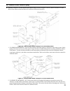
K. FUEL UNITS AND OIL LINES
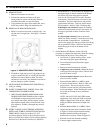
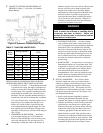
SINGLE-PIPE OIL LINES Standard burners are
provided with single-stage 3450 rpm fuel units with the
by-pass plug removed for single-pipe installations.
The single-stage fuel unit may be installed single-pipe
with gravity feed or lift. Maximum allowable lift is 8
feet. See Figure 15.
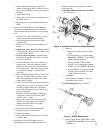
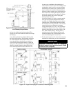
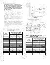
TWO-PIPE OIL LINES For two-pipe systems
where more lift is required, the two-stage fuel unit is
recommended. Table 4 (single-stage) and Table 5 (two-
stage) show allowable lift and lengths of 3/8-inch and
1/2-inch OD tubing for both suction and return lines.
Refer to Figure 16.
Be sure that all oil line connections are absolutely
airtight. Check all connections and joints. Flared
ttings are recommended. Do not use compression
ttings.
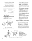
Open the air-bleed valve and start the burner. For clean
bleed, slip a 3/16" ID hose over the end of the bleed
valve and bleed into a container. Continue to bleed for
15 seconds after oil is free of air bubbles. Stop burner
and close valve.
Figure 15
Figure 16
Lift "H"
(See Figure)
Maximum Length of Tubing
"H" + "R" (See Figure)
3/8" OD
Tubing (3 GPH)
1/2" OD
Tubing (3 GPH)
0' 84' 100'
1' 78' 100'
2' 73' 100'
3' 68' 100'
4' 63' 100'
5' 57' 100'
6' 52' 100'
7' 47' 100'
8' 42' 100'
9' 36' 100'
10' 31' 100'
11' 26' 100'
12' 21' 83'
13' --- 62'
14' --- 41'
TABLE 4: SINGLE STAGE UNITS (3450 RPM)
TWO PIPE SYSTEMS
Lift "H"
(See Figure)
Maximum Length of Tubing
"H" + "R" (See Figure)
3/8" OD
Tubing (3 GPH)
1/2" OD
Tubing (3 GPH)
0' 93' 100'
2' 85' 100'
4' 77' 100'
6' 69' 100'
8' 60' 100'
10' 52' 100'
12' 44' 100'
14' 36' 100'
16' 27' 100'
18' --- 76'
TABLE 5: TWO-STAGE UNITS (3450 RPM)
TWO-PIPE SYSTEMS