


27
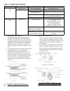
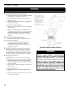
Figure 26: Adjusting Fuel Pump Pressure
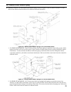
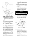
Figure 25A: Electrode Settings (Carlin EZ-HP)
G. ADJUST OIL BURNER BEFORE STARTING.
1. SET BURNER AIR BAND AND AIR SHUTTER,
see Table 9 at rear of manual.
2. Inspect Beckett head setting on left side of burner
by insuring the blue line MD(V1) or the line on the
label MB(L1) are aligned, readjust if necessary.
Refer to Figure 25.
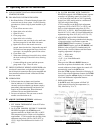
3. Inspect Carlin head setting on left side of burner to
ensure that the proper head positioning bar matches
the nozzle that is installed in drawer assembly.
Replace bar if necessary.
Carlin burners for boiler models CL3-140 and
CL4-210 have the higher ring rate nozzle installed
and two (2) loose nozzles with a head positioning
bar kit attached to the nozzle line. Refer to Table
9 for proper nozzle size, air settings and fuel pump
pressure setting based on desired ring rate.
If the desired ring rate is the lower GPH:
a. replace the factory installed high ring rate
nozzle with one of the loose lower ring rate
nozzles.
b. replace the factory installed head positioning bar
with the corresponding head bar that matches the
lower GPH nozzle installed, see Table 9.
c. change the factory air settings according to Table
9 and,
d. check the oil pump pressure and adjust if
necessary to the setting specied in Table 9, refer
to Paragraph H, Step 5 for details.
4. INSPECT RIELLO BURNER AIR DAMPER
AND TURBULATOR SETTING, readjust if
necessary, see Table 9a.
a. Remove pressure port/bleeder plug from fuel
pump and install Riello Combination Pressure
Gauge and Bleeder Valve Assembly.
5. OPEN ALL OIL LINE VALVES.
6. ATTACH A PLASTIC HOSE TO FUEL PUMP
VENT FITTING and provide a pan to catch the oil.
7. OPEN FLAME OBSERVATION DOOR on front of
boiler.
H. START OIL BURNER.
1. Open vent tting on fuel pump.
2. TURN ‘ON’ BURNER service switch and allow
burner to run until oil ows from vent tting
in a SOLID stream without air bubbles for
approximately 10 seconds.
3. Close vent tting and burner ame should start
immediately after pre-purge is complete. Pre-purge
prevents burner ame until 15 seconds has elapsed
after initial power is applied to burner. During
pre-purge, the motor and ignitor will operate but the
oil valve will remain closed. Refer to Oil Primary
Control Instructions for more details.
4.
ADJUST OIL PRESSURE for Beckett AFG burners
(shut the burner off).
a.
When checking a fuel unit's operating pressure, a
reliable pressure gauge may be installed in either
the bleeder port or the nozzle port. See Figure
26.
b. Locate oil pressure adjusting screw and turn
screw for appropriate pump pressure, refer to
Table 9 at rear of manual.
c. To check the cutoff pressure, deadhead a reliable
pressure gauge onto the copper connector tube
attached to the nozzle port. Run the burner for
a short period of time. Shut the burner off. The
pressure should drop and hold.
d. Remove the gauge and install bleeder port and/or
reconnect the nozzle port line.
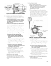
5. VERIFY/ADJUST FUEL PUMP PRESSURE for
Carlin EZ-HP burners.
a. Turn “off” burner service switch.