


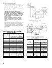

24
IV. Operating and Service Instructions
3. On WATER BOILERS WITH TANKLESS
HEATERS equipped with L7224 electronic aquastat
controller, set operating control (low limit [LL])
at 190°F and high limit (HL) at 210°F. Operating
control (low limit) setting must be a minimum of
20°F below high limit setting.
L7224 controller has the High Limit adjustment
range from 130°F to 240°F (55°C to 116°C), and
the Low Limit adjustment range from 110°F to
220°F (43°C to 104°C). High Limit Differential is
xed at 10°F (6°C), and Low Limit Differential has
adjustment range from 10°F (6°C) to 25°F (14°C).
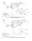
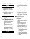
4.
ADJUSTING AQUASTAT CONTROLLER
SETTINGS. To discourage unauthorized changing
of Aquastat settings, a procedure to enter the
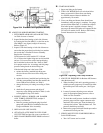
ADJUSTMENT mode is required. To enter the
ADJUSTMENT mode, press the UP, DOWN, and
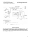
I buttons (refer to Figure 22) simultaneously for
three seconds. Press the I button until the feature
requiring adjustment is displayed:
• HL_ High Limit.
• LL_ Low Limit.
• Ldf Low Limit Differential.
• °F °C.
Then, press the UP and/or DOWN buttons to
move the set point to the desired value. After 60
seconds without any button inputs, the control will
automatically return to the RUN mode.
Note that L7224 Aquastat Controller will display all
four (4) above-listed adjustment features, but L7248
Aquastat Controller will not display Low Limit and
Low Limit Differential adjustment features.
5. DISPLAY READOUT
In the RUN mode, the Aquastat will ash "bt"
(boiler temp) followed by the temperature (i.e.,
220), followed by °F or °C.
A. ALWAYS INSPECT INSTALLATION BEFORE
STARTING BURNER.
B. FILL HEATING SYSTEM WITH WATER.
1. Hot Water Boilers: Fill entire Heating System with
water and vent air from system. Use the following
procedure on a Series Loop System installed as per
Figure 9:
a.
Close all but one zone valve.
b. Open drain valve on boiler.
c. Open ll valve.
d. Close purge valve.
e. Open relief valve on boiler.
f. Allow water to run out of drain valve until zone
has been purged of air and lled with water.
g.
Open zone valve to the second zone to be
purged, then close the rst. Repeat this step until
all zones have been purged but always have one
zone open. At completion open all zone valves.
h. Close drain valve.
i. When water discharges from relief valve, release
the lever on the top of the relief valve, allowing
it to close.
j. Continue lling the system until the pressure
gauge reads 12 psi. Close ll valve.
C. CHECK CONTROLS, WIRING AND BURNER to be
sure that all connections are tight and burner is rigid,
that all electrical connections have been completed and
fuses installed, and that oil tank is lled and oil lines
have been tested.
D. LUBRICATION
1. Follow instruction on burner and circulator
label to lubricate, if oil lubricated. Most motors
currently used on residential type burners employ
permanently lubricated bearings and thus do not
require any eld lubrication. Water lubricated
circulators do not need eld lubrication.
2. Do not over-lubricate. This can cause as much
trouble as no lubrication at all.
E. ADJUST CONTROL SETTINGS with burner
service switch turned “ON”.
1. SET ROOM THERMOSTAT about 10°F below
room temperature.
2. On WATER BOILERS WITHOUT TANKLESS
HEATERS equipped with L7248 electronic
aquastat controller, set High Limit (HL) at 180°F.
This temperature can be varied to suit installation
requirements. L7248 controller has the High Limit
adjustment range from 180°F to 240°F (82°C to
116°C). High Limit Differential is xed at 15°F
(8°C).
Figure 22: L7248/L7224 Circuit Board Layout -
Horizontal Mount