


12
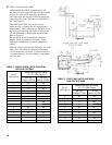
in left rear corner on top of boiler as shown in
Figure 1C. Tighten with wrench. Pipe discharge as
shown in Figure 11. Installation of the relief valve
must be consistent with ANSI/ASME Boiler and
Pressure Vessel Code, Section IV.
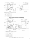
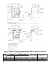
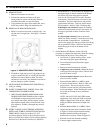
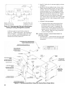
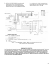
Figure 10: Recommended Piping for Combination
Heating & Cooling (Refrigeration) Systems
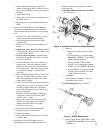
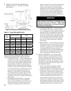
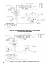
Figure 11: Recommended Boiler Piping For Gravity Return Steam Boiler
2. Install ¾" drain valve in wet return piping as shown
in Figure 11.
3.
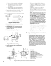
On boilers with rear tankless heater, factory wired
L4006A Aquastat Heater Control was not installed
in heater. Locate ¾" NPT Immersion Well, apply
sealant and thread into ¾" NPT tapping on heater.
Apply heat transfer paste (not furnished) to control
bulb and insert bulb into immersion well. Tighten
clamping screws to secure control to immersion
well. Secure 18/2 Control Cable Wire to jacket right
side panel with 5/16" cable clamp provided, refer to
Figure 1C.
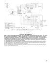
4. CONNECT FIELD WIRING
a. Connect the eld wiring to the pressure limit,
the R8239C Control Center, the LWCO and
the burner primary control. If equipped with
tankless heater, connect eld wiring from the
aquastat control to the R8239C Control Center's
"R-G" terminals. Make the wiring connections
as shown in Figure 19B.
H. CONNECT SUPPLY AND RETURN PIPING TO
HEATING SYSTEM.
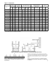
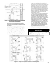
1. CLEARANCES — Steam and hot water pipes shall
have clearances of at least ½” from all combustible
construction.