


28
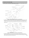
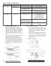
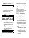
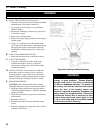
b. When checking a fuel pump’s operating pressure,
a reliable pressure gauge may be installed in
either the gauge port or the bleeder port. See
Figure 26A.
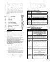
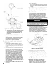
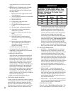
6. VERIFY/ADJUST OIL PRESSURE for Riello 40
burner.
Adjust oil pressure. Locate oil pressure adjusting
screw and turn screw to obtain proper pump
pressure, refer to Figure 8 and Table 9A.
I. ADJUST OIL BURNER WHILE OPERATING.
(ame present)
1. ADJUST DRAFT REGULATOR for a draft of
-0.02” (water gauge) over the re after chimney has
reached operating temperature and while burner is
running.
2. READJUST THE AIR DAMPER SETTING on the
burner for a light orange colored ame while the
draft over the re is -0.02”. Use a smoke tester and
adjust air for minimum smoke (not to exceed #1)
with a minimum of excess air. Make nal check
using suitable instrumentation to obtain a CO
2
of
11.5 to 12.5% with draft of -0.02” (water gauge)
in re box. These settings will assure a safe and
efcient operating condition. If the ame appears
stringy instead of a solid re, try another nozzle of
the same type. Flame should be solid and compact.
After all adjustments are made recheck for a draft of
-0.02” over the re.
3. READJUST THE TURBULATOR SETTING only
if necessary.
a. CL3 through CL5
Move the turbulator setting forward or back one
position at a time to optimize the smoke and CO
2
readings.
4. Turn “OFF” burner and remove Riello Combination
Pressure Gauge and Bleeder Valve Assembly.
Install pressure port/bleeder plug and tighten. Start
burner again.
5. FLAME FAILURE
The CL Series boiler controls operate the burner
automatically. If for unknown reasons the burner
ceases to re and the reset button on the primary
control has tripped, the burner has experienced
ignition failure. Before pressing the reset button call
your heating contractor immediately.
WARNING
Do not attempt to start the burner when excess oil
has accumulated, when the unit is full of vapor, or
when the combustion chamber is very hot.
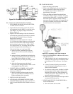
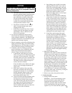
7. CAD CELL LOCATION AND SERVICE
The burner is supplied with a cadmium sulde ame
detector mounted at the factory, mounted on the
bottom of the electronic ignitor. See Figure 27. To
service cad cell or to replace the plug in portion,
swing open the ignitor. After service is complete, be
sure to fasten down the ignitor.
Figure 26A: Adjusting Fuel Pump Pressure
Figure 27: Cad Cell Location
J. CHECK FOR CLEAN CUT OFF OF BURNER.
1. AIR IN THE OIL LINE between fuel unit and
nozzle will compress when burner is on and will
expand when burner stops, causing oil to squirt from
nozzle at low pressure as burner slows down and
causing nozzle to drip after burner stops. Usually
cycling the burner operation about 5 to 10 times will
rid oil line of this air.
2. IF NOZZLE CONTINUES TO DRIP, repeat
Paragraph J, Step 1. If this does not stop the
dripping, remove cutoff valve and seat, and wipe
both with a clean cloth until clean, then replace