


3
ENVISION CONSOLE INSTALLATION MANUAL
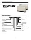
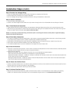
Model Nomenclature
CONSOLES
1-2 3 4-5 6 7 8 9 10 11 12 13 14 15-16 17
NC C 09 L 0 1 1 C N N A 1 SS A
Family Vintage
NC = Envision Console A = Current
Non-Standard Option Details
Cabinet Configuration SS = Standard Option
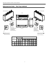
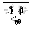
C = Chassis Only
W = Chassis with Cabinet
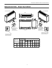
S = Chassis with Slope Top
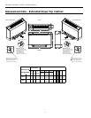
E = Chassis with Extended Slope Top
Unit Capacity Air Coil / Insulation Options
MBTUH @ 86
o
F EWT 1 = Formishield / Extended Range
09, 12, 15, 18 2 = Formishield / Standard Range
3 = No Coating / Extended Range
Piping Option 4 = No Coating / Standard Range
L = Left
R= Right (N/A with chassis only) Sound Kit
A = None
Voltage B = Blanket
0 = 208-230/60/1
2 = 265/60/1 Auxilliary Electric heat
N = None
C = 2.0 kW (09-12)*
Unit Control D = 3.0 kW (15-18)*
1 = CCM
2 = Versatec Motorized Oustide Air Damper (Field Installed)
4 = FX10 std. no communication - (only w/ t-stat control option 2) N = None
5 = FX10 w/Open N2 Com Card - (only w/ t-stat control option 2) M = Motorized Damper
6 = FX10 w/Lonworks Com Card - (only w/ t-stat control option 2)
7 = FX10 w/BacNet Com Card - (only w/ t-stat control option 2) Coax Options
C = Copper
Thermostat Control N = Cupronickel
1 = Unit mounted t-stat
2 = Remote wall-mounted t-stat