


16
ENVISION CONSOLE INSTALLATION MANUAL
System Cleaning and Flushing
Cleaning and Flushing
Prior to start up of any heat pump, the water circulating system must be
cleaned and flushed of all dirt and debris.
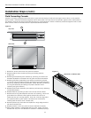
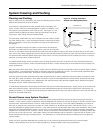
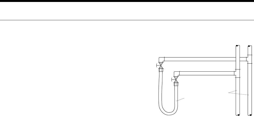
If the system is equipped with water shutoff valves, the supply and
return runouts must be connected together at each unit location (This
will prevent the introduction of dirt into the unit, see Figure 7). The
system should be filled at the water make-up connection with all air
vents open. After filling, vents should be closed.
The contractor should start the main circulator with the pressure reduc-
ing valve makeup open. Vents should be checked in sequence to bleed
off any trapped air and to verify circulation through all components of
the system.
As water circulates through the system, the contractor should check
and repair any leaks found in the piping system. Drain(s) at the lowest
point(s) in the system should be opened for initial flush and blowdown, making sure water fill valves are set at the same
rate. Check the pressure gauge at the pump suction and manually adjust the make-up water valve to hold the same posi-
tive pressure both before and after opening the drain valves. Flushing should continue for at least two hours, or longer if
required, until drain water is clean and clear.
The supplemental heater and/or circulator pump, if used, should be shut off. All drains and vents should be opened to
completely drain the system. Short-circuited supply and return runouts should now be connected to the unit supply and
return connections.
Refill the system with clean water. Test the system water for acidity and treat as required to leave the water slightly alkaline
(pH 7.5 to 8.5). The specified percentage of antifreeze may also be added at this time. Use commercial grade antifreeze
designed for HVAC systems only. Environol™ brand antifreeze is recommended..
Once the system has been filled with clean water and antifreeze (if used), precautions should be taken to protect the sys-
tem from dirty water conditions. Dirty water will result in system-wide degradation of performance, and solids may clog
valves, strainers, flow regulators, etc. Additionally, the heat exchanger may become clogged which reduces compressor
service life and can cause premature unit failure.
In boiler/tower application, set the loop control panel set points to desired temperatures. Supply power to all motors and
start the circulating pumps. After full flow has been established through all components including the heat rejector (re-
gardless of season), air vented and loop temperatures stabilized, each of the units will be ready for check, test and start up
and for air and water balancing.
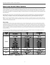
Ground Source Loop System Checkout
Once piping is completed between the unit pumping system and ground loop, final purging and charging of the loop is
needed. A high pressure pump is needed to achieve adequate flow velocity in the loop to purge air and dirt particles from
the loop itself. Antifreeze solution is used in most areas to prevent freezing. Flush the system adequately to remove as
much air as possible; then pressurize the loop to a static pressure of 40-50 PSI (summer) or 50-75 PSI (winter). This is
normally adequate for good system operation. Loop static pressure may decrease soon after initial installation, due to pipe
expansion and loop temperature change. Running the unit for at least 30 minutes after the system has been completely
purged of air will allow for the “break-in” period. It may be necessary to adjust static loop pressure (by adding water) after
the unit has run for the first time. Loop static pressure will also fluctuate with the seasons. Pressures will be higher in the
winter months than during the cooling season. This fluctuation is normal and should be considered when charging the
system initially.
Insure the pump provides adequate flow through the unit by checking pressure drop across the heat exchanger.
Usually 2.25-3.0 GPM of flow per ton of cooling capacity is recommended in earth loop applications.
Return Runout
Supply Runout
Mains
Rubber Hose
Runouts Initially
Connected Together
Figure 7: Flushing with Water
Shutoff Valve Equipped Systems