


30
ENVISION CONSOLE INSTALLATION MANUAL
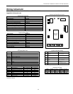
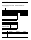
- MS/TP @ 19,200 Baud rate
- Limit devices to 40 on a single trunk line.
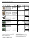
Control and Safety Feature Details
Emergency Shutdown
The emergency shutdown mode can be activated by a
command from a facility management system or a closed
contact on BI-2. The default state for the emergency shut-
down data point is off. When the emergency shutdown
mode is activated, all outputs will be turned off immediate-
ly and will remain off until the emergency shutdown mode
is de-activated. The first time the compressor starts after
the emergency shutdown mode has been de-activated,
there will be a random start delay present.
Lockout Mode
Lockout mode can be activated by any of the following
fault signals: refrigerant system high pressure, refrigerant
system low pressure, water coil low temperature (freeze
sensing), and condensate overflow. When any valid fault
signal remains continuously active for the length of its rec-
ognition delay, the controller will go into fault retry mode,
which will turn off the compressor. After the Compressor
short cycle delay, the compressor will attempt to operate
once again. If three consecutive faults occur in 60 minutes
during a single heating or cooling demand, the unit will go
into lockout mode, turning off the compressor, enabling
the alarm output, and setting the fan back to low speed
operation until the controller is reset. If the control faults
due to the low pressure input (BI-3) being open during
the pre-compressor startup check, the control will go into
lockout mode immediately, disabling the compressor from
starting and enabling the alarm output (BO-6). The lockout
condition can be reset by powering down the controller, by
a command from the BAS, or by the holding the ESC and
Return keys on the MUI for 5 seconds.
Water Coil Low Temp (Freeze Sensing) Limit (AI-5)
The water coil low temperature (freeze sensing) limit sen-
sor will monitor the liquid refrigerant temperature enter-
ing the water coil in the heating mode. If the temperature
drops below the water coil low temperature (freeze sens-
ing) limit trip point for the recognition delay period, the
condition will be recognized as a fault. The water coil low
temperature (freeze sensing) limit trip point will be factory
set for 30°F and will be field selectable for 15°F by remov-
ing a jumper wire on BI-5. The water coil low temperature
(freeze sensing) limit fault condition will be bypassed 2
minutes at normal compressor startup, to allow the refrig-
eration circuit to stabilize. If the water coil low temperature
(freeze sensing) limit sensor becomes unreliable at any
time compressor operation will immediately be suspended
until the problem is corrected. This should be displayed
as an alarm on the BAS and the MUI. This alarm will be
reported a “Water Low Temp Limit” fault.
High Pressure (BI-11)
The high-pressure switch shall be a normally closed (NC)
switch that monitors the systems refrigerant pressure. If
the input senses the high-pressure switch is open it must
disable the compressor output immediately and count the
fault. The compressor minimum on time does not apply if
the high-pressure switch opens. The compressor will not
restart until the compressor short cycle time delay has
been satisfied.
Low Pressure (BI-3)
The low-pressure switch shall be a normally closed (NC)
switch that monitors the systems refrigerant pressure. The
input shall be checked 15 seconds before compressor start
up to be sure the pressure switch is closed and then ignored
for the first 2 minutes after the compressor output (BO-2) is
enabled. If the switch is open continuously for (30) seconds
during compressor operation the compressor output (BO-2)
will be disabled. The compressor will not restart until the
compressor short cycle time delay has been satisfied.
Condensate Overflow
The condensate overflow sensing circuit will monitor the
condensate level as a resistance input to AI-3. If the con-
densate water level rises resulting in the input resistance
rising above the set point for the recognition delay period,
the condition will be recognized as a fault. The condensate
will be subjected to a (30) second lockout delay which
requires that the fault be sensed for a continuous (30)
seconds before suspending unit operation.
Alarm Output (BO-6)
The alarm output will be enabled when the control is in the
lockout mode and will be disabled when the lockout is reset.
Test Mode
Raising the zone temperature input (AI-1) reading to
180–220°F or by holding the ESC and down arrow keys on
the MUI for 5 seconds will put the control into test mode.
In test mode the random start delay and the compressor
fixed on delay time will both be shortened to 5 seconds
and the reversing valve will be allowed to cycle with out
shutting down the compressor. If an MUI is connected to
the control LED 8 will flash and the words “Test Mode En-
abled” will be shown on the LCD display when the control
is in test mode. Test mode will be disabled after a power
cycle, 30 minute timeout, or by holding the ESC and Up
arrow keys on the MUI.
Sequence of Operation
Power Fail Restart
When the controller is first powered up, the outputs will be
disabled for a random start delay. The delay is provided
to prevent simultaneous starting of multiple heat pumps.
Once the timer expires, the controller will operate normally.
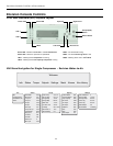
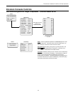
Envision Console Controls