


12
ENVISION CONSOLE INSTALLATION MANUAL
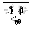
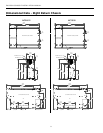
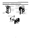
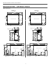
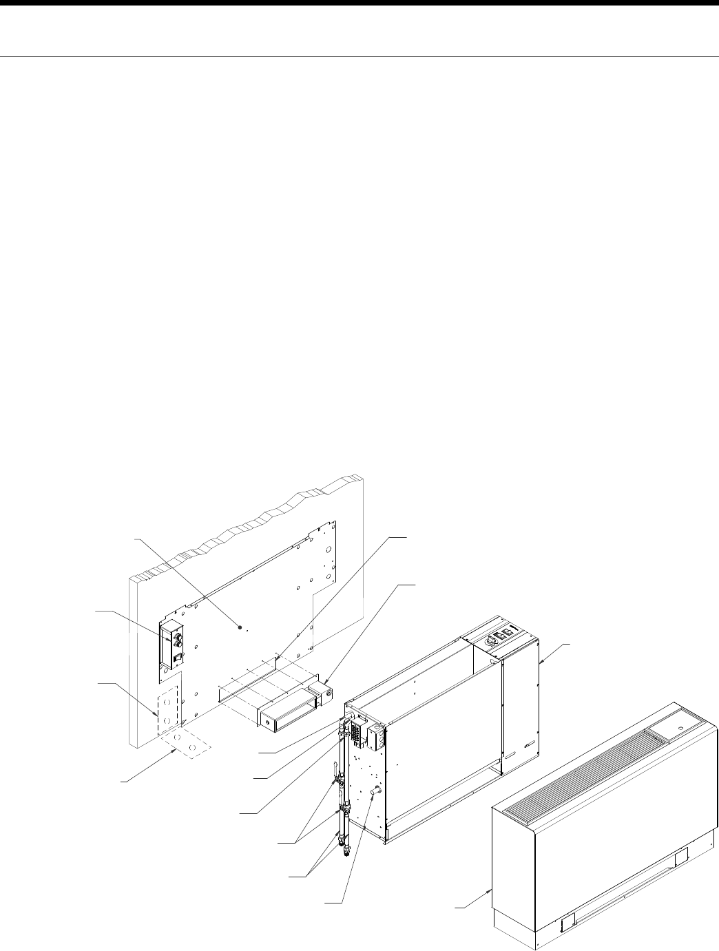
Installation Steps
Step 1: Unpack Equipment and Inspect for Damage
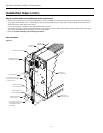
Step 2: Determine Equipment Location
Choose level flooring surface (Correctable with shims. Do not pitch towards drain.)•
Location of wall support and fasteners required to secure chassis backplate.•
Easy access for both installation and service. •
Consider availability and ease of wiring, water piping and condensate drain.•
No obstructions to block airflow in front of the unit.•
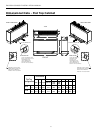
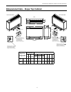
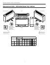
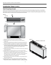
Step 3: Mark Unit Position
Ensure that floor is level. If shims are required, make sure that the entire compressor compartment area is uniformly •
shimmed and that the backplate mounting height is increased by the thickness of the shims used.
Position backplate in desired equipment location. To further reduce the operating sound level of the unit, 1/8-inch thick •
rubber matting may be placed under the chassis to eliminate vibration on hard flooring surfaces. (Make sure back plate
is level).
Mark and cut floor or wall penetrations for electrical wiring, water and condensate piping.•
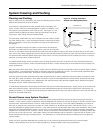
Optional Electrical Disconnect and Motorized Outside Air Damper
Mark and cut wall penetrations for field fabricated outside air duct sleeve.•
Align mounting holes with backplate and attach with screws supplied.•
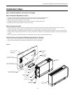
1=<A=:3
1/07<3B
1=<A=:3
16/AA7A
1=<23<A/B3
2@/7<:=1/B7=<
=>B7=</:6=A3A
0/::D/:D3A
=>B7=</:
>B>:C5A
=>B7=</:
E/B3@
=CB
E/B3@
7<
1=<A=:31/07<3B
0/19>:/B3
=>B7=</:
E/::>3<3B@/B7=<
4=@E/B3@1=<<31B7=<
4:==@>3<3B@/B7=<
4=@E/B3@1=<<31B7=<
4CA323:31B@71/:
27A1=<<31B=>B7=</:
;=B=@7H32
2/;>3@
=>B7=</:
;=B=@7H32
2/;>3@
=>3<7<5
Figure 1