


14
ENVISION CONSOLE INSTALLATION MANUAL
Installation Steps (cont.)
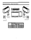
Step 5: Provide Line Voltage Wiring
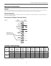
Check unit data plate located on control side of chassis for ampacity and fuse size.•
Remove electrical knockouts from chassis backplate.•
Run line voltage wiring through knockout and secure wiring to backplate or disconnect.•
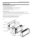
Step 6: Chassis Installation
Level and secure backplate to wall.•
Position the chassis against back plate. Drive (2) screws through holes in lip of backplate into top flange of chassis.•
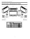
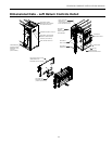
Step 7: Final Electrical Connection
Install flexible electrical conduit between the backplate or electrical disconnect and the unit mounted junction box. •
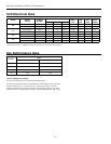
Make final wiring connections in disconnect and junction box, taking care to replace all covers when done. Wiring must •
conform to NEC and/or all local codes. Refer to Electrical Data.
NOTE: It is necessary to make final wiring connections prior to securing unit chassis to back plate on right-hand piping
models with electrical disconnect.
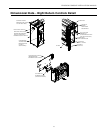
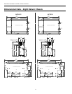
Step 8: Final Water Connection
For ease of installation and sound attenuation, high pressure (recommended) flexible hoses with a swivel fitting should •
be provided. Apply Teflon® tape or sealant compound to threaded hose fittings.
Combination shut-off/balancing valves should be installed on both the supply and return water lines of the unit.•
Flow control valves should be installed on the water discharge line.•
It is recommended that P/T ports be installed on the supply and return water lines.•
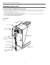
Step 9: Set Unit Controls
Locate the “continuous fan/cycle fan” switch within the electrical compartment of the chassis and set to desired position.•
(Remote wall thermostat units do not use this optional switch.)
Optional Control Settings-•
Remote Thermostat - Run low voltage wiring from unit to the desired thermostat location.
Mount and wire thermostat according to manufacturer’s recommendations.
Motorized Outside Air Damper - Locate the “damper on/damper off” damper switch within the electrical compartment
of the chassis and set to desired position.
Emergency Electrical Heat - Locate the “electric heat/normal/boilerless” control switch within the electrical compart-
ment of the chassis and set to desired position.
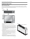
Step 10: Secure the Cabinet Cover
Position and lower cabinet over unit chassis. Apply pressure to the front of the cabinet to ensure that the back lip of the •
cabinet hooks over the tabs provided on the backplate.
Secure cabinet to chassis with mounting screws provided.•
Step 11: Perform Final Unit Check
Measure the pressure drop across the water coil and monitor water or air temperatures in both heating and cooling •
modes. The measured values should fall within the acceptable ranges shown in the Startup Performance table.