


26
ENVISION CONSOLE INSTALLATION MANUAL
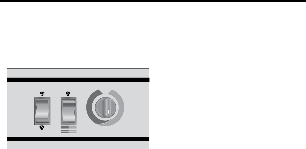
The user selects either “Heat/Cool” or “Fan Only” on the
mode switch, then either “High” or “Low” at the fan speed
switch. The temperature can be controlled by rotating the
thermostat control knob.
The “Fan Only” setting provides constant fan operation.
In the “Heat” mode, a call for heat by the thermostat closes
the compressor contactor contacts, energizing the com-
pressor, which will run until the thermostat is satisfied.
In the “Cool” mode, a call for cooling by the
thermostat energizes the reversing valve and closes the
compressor contactor contacts, energizing the compres-
sor, which will run until the thermostat is satisfied.
The emergency electric heat operation in the “Heat/Cool”
mode is subject to the setting of the internally mounted
mode switch. The optional, factory installed electric heat
will operate when the internally mounted mode switch is
in the “Emergency Heat” mode. In the “Heat” mode, a call
for heating energizes the fan and electric heater contactor,
energizing the electric heat elements and fan, which will
run until the thermostat is satisfied. When the internally
mounted mode switch is in the “Normal/Boilerless” mode
the unit operates in its normal “Heat/Cool” operation,
unless there is an aquastat controller. When the normally
open circuit of the aquastat closes and the unit is in the
heating mode, it will switch to the “Emergency Heat”
condition until the thermostat is satisfied or the aquastat
opens restarting the compressor.
If either the low or high pressure safety switches are
opened, the compressor and reversing valve are disabled
by the lockout relay. Unit operation will resume only after
the voltage to the unit is interrupted or the mode switch is
placed in the “Off” position.
If the electric heat limit switches are opened, the electric
heat is disabled.
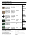
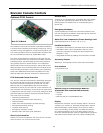
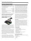
Optional Versatec Microprocessor
Control Features
The Versatec microprocessor board provides control of
the entire unit as well as outputs for status modes, faults
and diagnostics. The control system is a microprocessor-
based control board that is located in the unit control box.
This feature is available for either unit mounted controls
or optional remote wall mounted thermostat. A 9-pin low
voltage terminal strip provides all necessary terminals for
the wall mounted thermostat.
Startup
The unit will not operate until all the inputs and safety
controls are checked for normal operating conditions.
Fault Retry
All faults are retried twice before finally locking the unit
out to prevent nuisance service calls.
Component Sequencing Delays
Components are sequenced and delayed for optimum unit
performance.
Short Cycle Protection and Random Start
The control allows a minimum on or off time of 5 minutes
for short cycle protection. A random time delay of 0 to
30 seconds is generated after each power-up to prevent
simultaneous start up of all units within a building after the
release from an unoccupied cycle or power loss.
Night Setback
A grounded signal to common or connecting 24 VAC to
the NS terminal will initiate the night setback mode.
Load Shed
A grounded signal to common or connecting 24 VAC to
the LS terminal places the controller into the load shed
mode. The compressor will become disabled and the fan
will start upon a thermostat call for heating or cooling.
Emergency Shutdown
A grounded signal to common or connecting 24 VAC to
the ES terminal places the controller into the emergency
shutdown mode. The compressor and fan operation are
suspended while in the emergency shutdown mode.
Condensate Overflow Protection
The board incorporates an impedance liquid sensor at the
top of the condensate drain pan. Upon a continuous 30-
second sensing of the condensate, the cooling operation of
the unit is suspended.
Safety Controls
The microprocessor board receives separate signals from
a high pressure switch for safety, a low pressure switch to
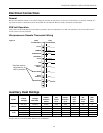
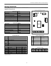
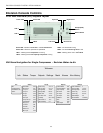
Figure 6: Unit Mounted Control
Envision Console Controls