


18
ENVISION CONSOLE INSTALLATION MANUAL
Electrical Connections
General
Be sure the available power is the same voltage and phase as that shown on the unit serial plate. Line and low voltage wir-
ing must be done in accordance with local codes or the National Electric Code, whichever is applicable.
208 Volt Operation
All Envision Series 208/230 units are factory wired for 230 volt operation. For 208 volt operation, the red and blue trans-
former wires must be switched.
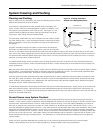
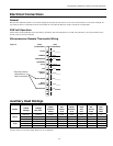
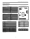
Microprocessor Remote Thermostat Wiring
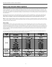
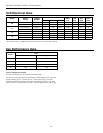
Auxiliary Heat Ratings
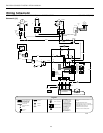
TB
O
G
Y
C
R
L
S
X2
X1
W2
Field
Connections
Unit
Connections
24 VAC
COMMON
COMPRESSOR
REVERSING
VALVE
FAN
LOCKOUT
SIGNAL
SHUTDOWN
NIGHT
SETBACK
LOAD SHED
Requires common
connections or 24
VAC for activation
Red
Black
Yellow
Orange
Green
Brown
Blue
Violet
Pink
Figure 5
Model
Rated
Voltage
Voltage
Min./Max.
Heater
Element
Watts
Fan
Motor
FLA
Heater
Element
FLA
Total
Unit
FLA
Min.
Circuit
Amp.
Max.
Fuse/
Brkr.
09-12
208/60/1 197/254 2000 0.50 9.62 10.1 12.7 15
230/60/1 197/254 2445 0.50 10.63 11.1 13.9 15
265/60/1 239/292 2000 0.55 7.55 8.1 10.1 15
15-18
208/60/1 197/254 3000 0.69 14.42 15.1 18.9 20
230/60/1 197/254 3668 0.69 15.95 16.6 20.8 25
265/60/1 239/292 3000 0.65 11.32 12.0 15.0 15
3/4/08
Always refer to unit name plate data prior to installation.