


23
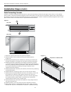
ENVISION CONSOLE INSTALLATION MANUAL
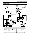
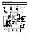
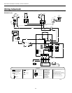
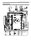
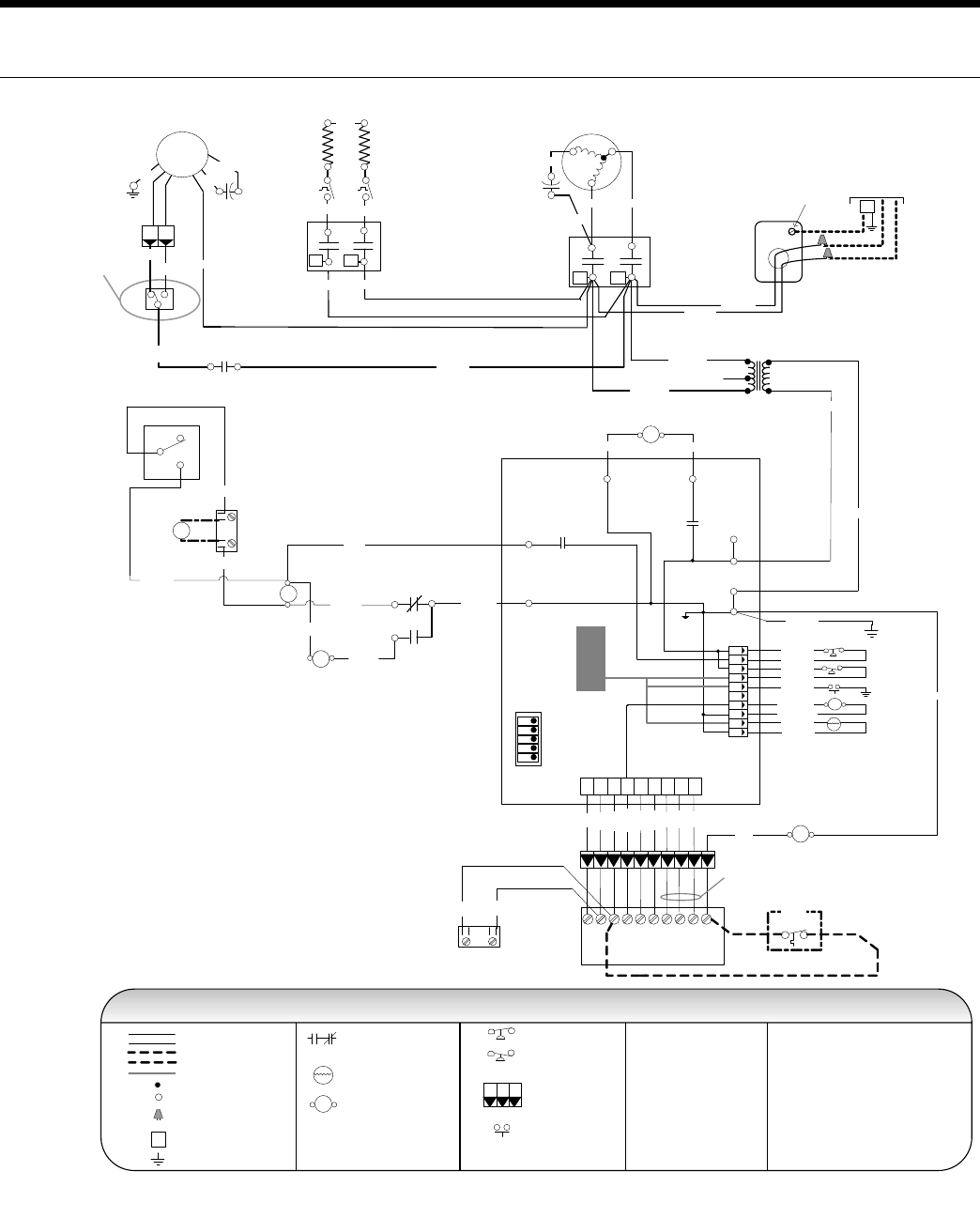
Wiring Schematic
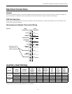
208-230-265/60/1VERSATEC CONTROL - EH & REMOTE WALL THERMOSTAT
Schematic [A]
Transformer
24V
Cap
Brn/Wht
Brn
Grn
H L
PSC
Fan
Motor
CC
T2 T1
Compressor
C
R
S
Tan (36)
Red
Blu
L1L2
Relay Contacts-
N.O., N.C.
Thermistor
Relay coil
Switch - High pressure
Switch - Low pressure
Polarized connector
Condensate Overflow
Factory low voltage wiring
Factory line voltage wiring
Field low voltage wiring
Field line voltage wiring
Internal junction
Quick connect terminal
Wire nut
Field wire lug
Ground
L1
Legend
5 - Switch blue and red wires for 208V operation.
T
1
3
2
P
Notes:
1 - Requires common connection or 24 VAC for
activation.
NOTE 5
Red 208V
Blue 230V
Blk
Black(27)
R
C
C
R
CC
CCG
OnOff
Test / Normal
Loop / Well
P2
P1
SW1
Inputs / Normal
Outputs / Normal
1
2
3
4
5
Motorized Valve / Normal
FAN
FAN
COM
CPU
FS
LP
HP
RV
CO
LSNSESLOGOYCR
Yellow
Black/White
T
Black (47)1
6
2
7
3
8
4
9
5
10
DC voltage PCB traces
High
Low
Fan Speed
Switch
RB
Blue 265V
4 - Check installlation wiring information for
specific thermostat hookup instructions.
Red
Black (25)
RB
Gray (42)
White (28)
Black(29)
Red (30)
Damper
Motor
Off
On
DAMPER MODE
DT
D
Blue/Wht (35)
MV
Black (31)
Red (32)
Handi - Box
Ground
Lug
Unit
Power Supply
208-230/60/1 or
265-277/60/1
G
CR Y1 O G L S
Terminal Board
X2 X1 W1
Red
Black
Yellow
Orange
Brown
Green
NOTE 2
Violet
Pink
Blue
1 3
4 2
NOTE 1
ES – Emergency Shutdown
Black/
White
Black/
White
Black Com
E1
EH
T2 T1
L1
White
White
L2
Blue (40)
LS1
LS2
Black
Tan (41)
E1
4
2
5
Black (37)
Blue (38)
Red (39)
AQ
NOTE 3
White
2 - When field installed 24VAC motorized
valve is used, connect to C and Y or SV terminals.
3 - Optional field installed aquastat for use with single heat
Blue/Wht (36)
Black (46)
Blue (45)
Blue (44)
Brown(43)
Orange (42)
Orange (41)
Yellow
Yellow
Green (00)
Black (22)
Orange (21)
EH
CC
White (34)
Brown (43)
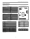
Legend
Microprocessor – with Remote Wall Stat & Electric Heat
Console Unit – Wiring Schematic 208-230-265/60/1
97P786-04 6/10/08
EH – Electric Heat Contactor
AQ – Aquastat
CC – Compressor Contactor
CO – Condensate Overflow
E1 – Electric Heat Relay
FS – Freeze Sensing Device
HP – High Pressure Switch
LP – Low Pressure Switch
LS – Loadshed
NS – Night Setback
RB – Blower Power Relay
RV – Reversing Valve Coil
SW1 – DIP Switch #1
MV – Motorized Valve
Red(19)
DT – Damper Terminal Block