


32
ENVISION CONSOLE INSTALLATION MANUAL
ECM2 Blower Operation
Fan speeds will be selected through the user interface or
the facility management system. There will be a total of 12
speeds selectable with only three being selected at any
one time. The lowest numbered speed selection set to ON
will select the low-speed fan setting, the middle selection
set to ON will select the medium-speed fan setting and
the highest selection set to ON will select the high-speed
fan setting. If all selections are set to OFF the software
shall select speed setting 10 for low-speed, 11 for medium-
speed, and will select speed setting 12 for high speed. If
only one selection is set to ON, that selection will set the
low-speed fan setting, the medium-speed setting will be 11,
and the high-speed setting will be speed 12. The maximum
low-speed setting will be speed 10 and the minimum high-
speed setting will be speed 3.
In addition there is a low limit
setting in the software to prevent the ECM2 fan speed from
being set below acceptable limits for each unit size.
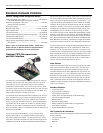
ECM2 Fan air flow “Soft Switch Settings”
A set of 12 “soft switches” accessible through the user
interface or building automation system are used to select
the three fan speed settings for the ECM2 fan motor.
The 12 soft switches work in exactly the same way as the
hardware switches used on the Premier control (Refer to
Fan Performance Data - ECM2 Motor for proper settings).
No more than three soft switches may be set to the “ON”
position. The first “ON” switch (the lowest number switch)
determines the “low speed fan” setting. The second de-
termines the “medium speed fan” setting, and the third
determines the “high speed fan” setting.
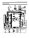
Emergency Heat/Network Enabled Output (BO5)
This output is set from the factory to enable/disable
emergency heat. If a problem occurs with the unit result-
ing in the compressor being locked out in heating mode,
the control will automatically enable this output to turn
on field installed electric heat. This output is interlocked
with the fan proving input BI-6 (Fan proving sensors must
be field supplied and installed). BI-6 must be connected
to PB2 position 3 (see unit schematic) in the field if no fan
proving sensor is desired. There is a configurable parame-
ter available through a BAS network that must be enabled
if this output is to be commanded over the BAS network.
MUI Alarm History Reporting
If a fault occurs the fault will be recorded in history for
display on the medium user interface in the History Menu.
Each fault type will be displayed in the history menu with
a number between 0 and 3. A reading of 3+ will mean
that fault has occurred more than three times in the past.
The history menu can be cleared with a power cycle only.
Alarm date and time are not included in the history.
Inputs & Outputs Configuration
Field Selectable Options
Water Coil Low Temp (Freeze Sensing) Limit Set Point (BI-5)
The water coil low temperature (freeze sensing) limit set
point input allows you to adjust the water coil low tem-
perature (freeze sensing) limit set point (AI-5). When the
jumper is installed on BI-5 (Wire #24) the water coil low
temperature (freeze sensing) limit set point is factory set
for 30°F. When the jumper on BI-5 (Wire #24) is removed
the water coil low temperature (freeze sensing) limit set
point will be 15°F.
Accessory Outputs (BO-7 and BO-8)
Accessory Output 1 will be energized 90 seconds prior to
the compressor output being energized. Accessory Output
2 will be energized with the fan output (BO-1). When the
corresponding compressor output is turned off the acces-
sory output will be deactivated immediately. These outputs
are selectable for normally open or normally closed opera-
tion through the Medium User interface or through the
Building Automation System.
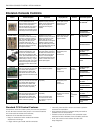
Control Accessories
Zone Sensors
TAXXJ02 Room Command Module•
TAXXA01 LCD Room Command Module•
A99 Sensor•
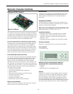
MUI (LCD User interface) for diagnostics
and commissioning.
MUIK1 - Panel Mount, Portable•
MUIK2 - Wall Mount•
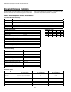
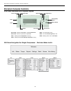
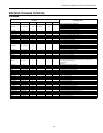
Envision Console Controls
Input Name Input Output Name Output
Zone Temp 1 AI 1 Fan Enable BO1
Relative Humidity Input AI 2 Comp – Low Capacity BO2
Condensate Level AI 3 Reversing Valve BO3
Universal Temp Input AI 4 Comp – Full Capacity BO4
Water Coil Low Temperature Limit AI 5 Network Output/EH Output BO5
Warm/Cool Adjust and Temp Occ AI 6 Alarm BO6
Accessory 1 Output BO7
Occupied BI 1 Accessory 2 Output BO8
Emergency Shutdown BI 2 Network Controlled Output B09
Stage 1 Low Pressure BI 3
Network Viewable Input 1 BI 4 ECM2 Fan PWM1
Water Coil Low Temp Limit Set Point BI 5 Network Controlled Output PWM2
Network Viewable Input 2 BI 6
Thermostat Y1 BI 7
Thermostat Y2 BI 8
Thermostat O BI 9
Thermostat G B10
Stage 1 High Pressure BI11
Compressor Proving BI12
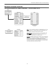
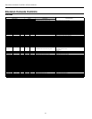
XP10 Expansion Card
Input Name Input Output Name Output
Unused AI 1 Unused BO 1
Unused AI 2 Unused BO 2
Unused AI 3 Unused BO 3
Unused AI 4 Unused BO 4
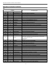
SINGLE and DUAL STAGE WATER-TO-AIR