


27
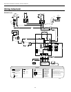
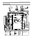
ENVISION CONSOLE INSTALLATION MANUAL
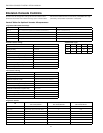
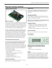
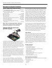
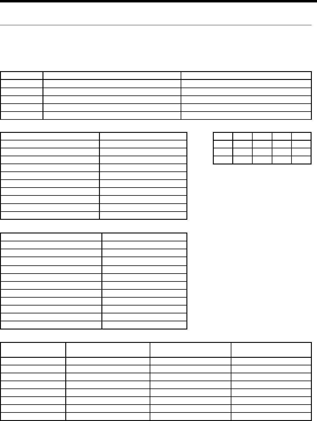
Envision Console Controls
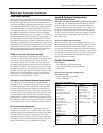
Mode Inputs Fan Comp RV
Htg
Y ON ON OFF
Clg
Y,O ON ON ON
Fan
G ON OFF OFF
Switch OFF ON
SW1 - 1
Test - Selected timings sped up to facilitate troubleshooting Normal - Standard timings
SW1 - 2
Loop - Closed loop freeze sensing setting (15°F) Well - Open loop freeze sensing setting (30°F)
SW1 - 3
Commercial - Enables NS features when TA32U02 thermostat is used Normal - Standard thermostat operation
SW1 - 4
IO Display* - Enables Input/Output display on external LED board Normal* - Unit status display
SW1 - 5
Configures board for 2-speed compressor without fan Configures board for 2-speed compressor with fan
Logic Board DIP Switch Settings
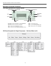
Blower off delay
30 seconds
Compressor on delay
10 seconds
Short cycle delay
5 minutes
Miniumum compressor on time
2 minutes (except for fault condition)
High pressure fault recognition delay
Less than 1 second
low pressure fault recognition delay
30 seconds
Freeze sensing fault recognition delay
30 seconds
Condensate overflow fault recognition delay
30 seconds
Low pressure fault bypass delay
2 minutes
Freeze sensing fault bypass delay
2 minutes
Power on delay
5 minutes
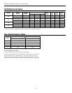
Normal Control Timing Operational Logic
Blower off delay
5 seconds
Compressor on delay
2 seconds
Short cycle delay
15 seconds
Miniumum compressor on time
5 seconds (except for fault condition)
High pressure fault recognition delay
Less than 1 second
low pressure fault recognition delay
30 seconds
Freeze sensing fault recognition delay
30 seconds
Condensate overflow fault recognition delay
30 seconds
Low pressure fault bypass delay
0 seconds
Freeze sensing fault bypass delay
0 seconds
Power on delay
15 seconds
Fault off time
5 minutes
Test Control Timing
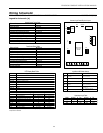
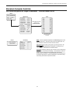
LED
Current Fault Status
SW1 - #4 On, SW2 On
Inputs
SW1 - #4 Off, SW2 Off
Outputs
SW1 - #4 Off, SW2 On
Drain Drain pan overflow Y Compressor
Water Flow FS thermistor (loop <15°F, well <30°F) G FAN
High Press High pressure >600 PSI O O
Low Press Low pressure <40 PSI ES ES
Air Flow Not used NS NS
Status Not used LS LS
DHW Limit Not used Not used Not used
HWD SW2 in the On position Off position On position
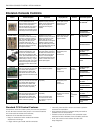
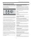
Diagnostic Modes
prevent loss of refrigerant charge and a low suction tem-
perature thermistor for freeze sensing. Upon a continuous
30-second measurement of the fault (immediate for high
pressure), compressor operation is stopped.
Control Tables for Optional Versatec Microprocessor