


88 Maintenance and Service
S
ection 5: Maintenance and Service 6888Xi Advanced Electronics Instruction Manual
December 2012 PN 51-6888Xi
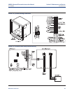
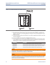
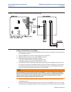
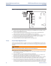
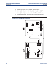
FIGURE 5-9. Power Supply Board Wiring
8. Slide the Power Supply board into the mating slots in the 6888Xi Enclosure. Make sure the
board is correctly aligned in the slots.
9. Install and tighten the bracket mounting screws. Two new screws are provided in the
replacement kit and should be used if the 6888Xi screws are damaged.
10. Connect the ribbon cable to the Power Supply board. A new ribbon cable (7, Figure 5-1) is
provided in the replacement kit and should be used if the 6888Xi cable is damaged.
11. Connect the AC power plug to the Power Supply board.
12. Swing the 6888Xi cover up and tighten the four mounting screws.
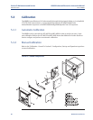
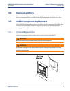
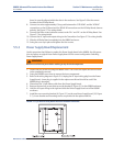
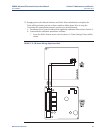
5.5.4 Front Panel Replacement
Use the procedure that follows to replace the front panel on the 6888Xi.Replacement kits with
and without the CPU board are available. Use the instructions that apply to the replacement kit
you have.
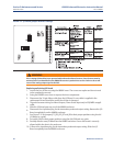
Replacing Front Panel Assembly without CPU Board
1. Loosen the four screws securing the 6888Xi cover. The screws are captive and do not need
to be completely removed.
2. Swing the 6888Xi cover down to expose the inner components.
3. Disconnect the 14-pin ribbon cable going to the Power Supply board. A new cable is sup-
plied in the replacement kit and should be used if the old one is damaged.
4. Disconnect the 10-pin ribbon cable(s) going to the I/O Board(s). One new cable is supplied
in the replacement kit and should be used if either of the ribbon cables are damaged.
5. Remove the wire hinge from the right side of the 6888Xi cover. A paper clip or similar device
can be inserted into the hole on the left side of the cover to push the hinge out of the cover.
A new hinge pin is supplied in the replacement kit and should be used if the old one is damaged.
WARNING
Disconnect and lock out power before working on any electrical components.