


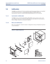
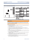
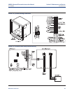
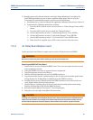
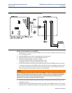
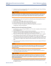
11. Reinstall wiring for Alarm Outputs, Flame Status Input and/or SPS/IMPS as applicable. See
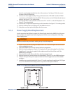
Figure 5-4 and Figure 5-5 for wiring diagrams. See Figure 5-6 for I/O board positions in the
6888Xi enclosure.
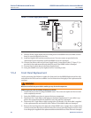
12. Connect the ribbon cable to the I/O Board. A new cable is supplied and should be used if the
old one is damaged.
13. Swing the 6888Xi cover up in place and tighten the four screws.
14. Prior to operating the O
2
Probe and the 6888Xi, all optional software enhancements (previ-
ously enabled or not) must be enabled. Notify Rosemount Analytical Inc. and reference the
following part numbers to enable the related software options:
84 Maintenance and Service
S
ection 5: Maintenance and Service 6888Xi Advanced Electronics Instruction Manual
December 2012 PN 51-6888Xi
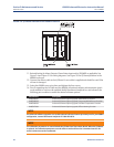
F
IGURE 5-6. I/O Board Positions in the 6888Xi Enclosure
Part Number Description
6A00269G01 Enhanced Software Option Upgrade, Stoichiometric Function
6A00269G02 Enhanced Software Option Upgrade, Programmable Reference Function
6A00269G03 Enhanced Software Option Upgrade, Extended Temperature Function
6A00267604 Enhanced Software Option Upgrade, Diffuse Warning Function
NOTE
For enhanced software upgrades or to enable optional software features previously used in your 6888Xi
configuration, contact Rosemount Analytical at 1-800-433-6076.
NOTE
The calibration parameters are stored in both the I/O Board and Transmitter Board. When the I/O Board
is replaced, the calibration parameters must be either transferred from the Transmitter Board or the
entire instrument must be recalibrated.