


48 Configuration, Startup and Operation
S
ection 3: Configuration, Startup and Operation 6888Xi Advanced Electronics Instruction Manual
December 2012 PN 51-6888Xi
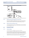
3.6.1 Field Communicator Signal Line Connections
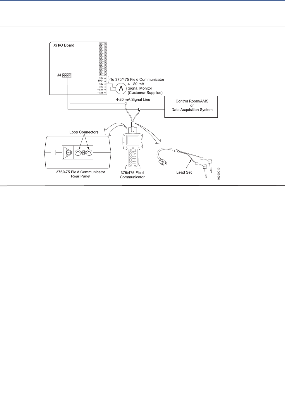
When working at the 6888Xi, the 375/475 Field Communicator can be connected directly to
test points TP21 and TP22 on the 6888Xi I/O Board as shown in Figure 3-5. The AM+ and AM-
test points are provided to monitor the 4-20 mA signal without breaking into the loop.
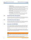
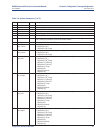
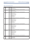
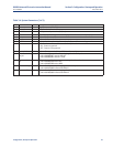
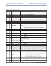
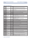
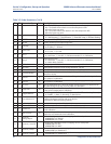
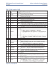
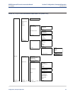
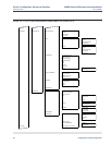
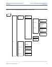
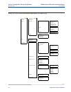
3.6.2 Field Communicator Menu Trees
Connect the 375/475 Field Communicator in the 6888Xi (6888Xi-to-DCS) 4-20 mA signal loop
or to the 6888Xi terminals as shown in Figure 3-5 and refer to Figure 3-6 for the 375/475 Field
Communicator 6888Xi menu tree.
3.7 Parameter Setup
3.7.1 Test Gas Values
Use a Field Communicator or the 6888Xi to set test gas values for calibration.
When using the 6888Xi with an SPS4001B or IMPS the test gas values for Gas 1 and Gas 2 corre-
spond with Lo Gas and Hi Gas, respectively. Care must be taken to ensure the test gas values are
properly matched and the test gases are plumbed correctly to the SPS4001B or IMPS. Failure to
do so may cause errors on the calibration serquence or trigger an error if tolerance check is set on.
A 6888Xi shipped from the factory has test gas values for low and high set to 0.4% and 8.0%
respectively. This same process must be performed any time an I/O Board is replaced.
F
IGURE 3-5. 375/475 Field Communicator Connection at the 6888Xi