


Configuration, Startup and Operation 47
6
888Xi Advanced Electronics Instruction Manual Section 3: Configuration, Startup and Operation
PN 51-6888Xi December 2012
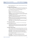
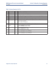
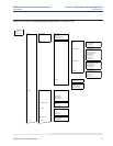
TX IOB Parameter Name Unit Description
Y Y Slope mV/Dec
Current calibration slope. This is the slope value that was calculated as a result of
the last successful calibration.
Y Y Constant mV
Current calibration constant. This is the constant value that was calculated as a
result of the last successful calibration.
Y Y I
mpedance
o
hm
C
ell Impedance. This is the sensor resistance that was calculated as a result of
t
he last successful calibration.
Y Y Time Days ago Time stamp of the last successful calibration.
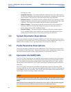
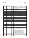
Y Y Cal Logs | Slope mV/Dec
Previous calibration slope. There are ten calibration results. 1 is the most recent
and 10 is the least recent calibration slope
YYCal Logs | Constant mV
ration constant. There are ten calibration results. 1 is the most recent and 10 is
the least recent calibration constant.
YY
Cal Logs |
Impedance
ohm
Previous Cell Impedance. This is the sensor resistance that was calculated as a
result of previous successful calibration. . There are ten calibration results. Index
1 is the most recent and Index 10 is the least recent sensor resistance measured.
YYCal Logs | Time Days ago
Time stamp of the previous successful calibration. There are ten calibration time
stamp. Index 1 is the most recent and Index 10 is the least recent time stamp.
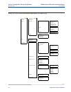
NYBad Slope mV/Dec Failed calibration slope.
NYBad Constant mV Failed calibration constant.
YYCal Result --
Calibration result:
0 = None, 1 = Success, 2 = Failed Constant, 3 = Failed Slope,
4 = Failed Temperature, 5 = Gas 1 Tolerance Error, 6 = Gas 2 Tolerance Error,
7-10 (future), 11 = AutoCal No Resp, 12 = AutoCal OutofSync,
13 = AutoCal Abort, 14 = No Solenoid, 15 = WarmUp Abort, 16 Alarm Abort
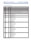
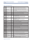
NYDelta Imp -- Delta impedance since last calibration.
NYCal Step --
This represents the step of the calibration cycle is in:
0 = Idle, 1 = Reserved, 2 = Apply Gas 1, 3 = Flow Gas 1, 4 = Read Gas 1,
5 = Apply Gas 2, 6 = Flow Gas 2, 7 = Read Gas 2, 8 = Cal Abort, 9 = Stop Gas,
10 = Purge
NYTime Remain sec Time remaining in the present calibration cycle state.
NYProcess mV
Cell mV reading just prior to start of calibration. (Diagnostic parameter for
Diffuser Warning feature.)
NYDiag State --
The state of the Diffuser Warning state machine: (Diagnostic parameter for
Diffuser Warning feature.)
0 = Idle, 1 = Wait Gas 1, 2 = Stable Gas 1, 3 = Read Gas 1, 4 = Wait Gas 2,
5 = Stable Gas 2, 6 = Read Gas 2, 7 = Wait Process, 8 = Rtn Process
NYInit Resp sec
The time it takes for the first calibration test gas to reach the sensor cell after the
solenoid is energized. (Diagnostic parameter for Diffuser Warning feature.)
NYProcess Resp sec
The time it takes to see the initial response of the process after the gas 2 sole-
noid is turned off. (Diagnostic parameter for Diffuser Warning feature.)
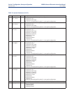
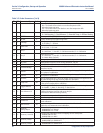
NYRtn Process sec
The time it takes from the initial response of the process until the process value
has stabilized close to the value of the process when the calibration started.
(Diagnostic parameter for Diffuser Warning feature.)
NYO2 Rate Change mV/s
The O2 cell mV rate of change. (Diagnostic parameter for Diffuser Warning
feature.)
NYDiff T90 sec
The time it takes from the gas-2 solenoid is turned off to return to 90% of the
process when the calibration started. (Diagnostic parameter for Diffuser
Warning feature.)
NYPurge Time % %
The percent of purge time used. This parameter can be used to estimate amount
of diffuser pluggage. (Diagnostic parameter for Diffuser Warning feature.)
NYDiff Warn --
The reason of the Diffuser Warning alarm: (Diagnostic parameter for Diffuser
Warning feature.)
0 = None, 1 = Gas 1 No Detect, 2 = Gas 2 No Detect, 3 = Gas 1 Unstable,
4 = Gas 2 Unstable, 5 = Process No Detect, 6 = Purge End Premature,
7 = Fail Reach Process, 8 = Diffuser Plugging, 9 = Constant Shifting
Table 3-5. Probe Parameters (4 of 4)