


42 CPU Module labeling and LED indicators
Section 3: Electrical installation Daniel 3818 LNG Liquid Ultrasonic Meter Installation Manual
May 2012 3-9000-771 Rev A
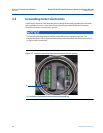
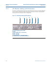
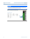
3.5.1 CPU Module labeling and LED indicators
The meter’s metrology mode and the status of the data transfer from the Acquisition Module to
the CPU Module is indicated via light-emitting diode (LED) status indicators. The Write PROT.
switch prevents overwriting the meter’s configuration,
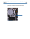
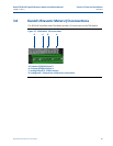
Figure 3-3 CPU Module labeling and LED indicators
A.
B.
C.
D.
E.
A. Acquisition/Measurement mode
B. Power
C. RX (RS-485/RS-232) - receiving data
D. LED 4 - not used
E. LED 5 - not used
F. TX (RS-485/RS-232) - transmitting data
F.
G.
G. Link (Eth1 Link) - user Ethernet connection