


Daniel 3818 LNG Liquid Ultrasonic Meter Installation Manual Section 1: Introduction
3-9000-771 Rev A May 2012
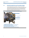
3818 LNG Liquid Ultrasonic Flow Meter design 7
Computer simulations of various velocity profiles demonstrate that eight measurement paths
provide an optimum solution for measuring asymmetric flow. The Daniel 3818 LNG Liquid
Ultrasonic Flow Meter utilizes eight cross-bore, parallel-plane measurement paths to offer a high
degree of accuracy, repeatability, and superior low-flow capabilities without the compromises
associated with conventional technologies. The meter is comprised of two 3810 Transmitter
Electronics, designated as co-located primary (master) and secondary (slave) electronics. A syn-
chronization cable connects the primary and secondary Acquisition Modules at the J6 terminal
block and the liquid ultrasonic flow meter firmware controls the transducers firing sequencing.
The Daniel 3818 LNG Liquid Ultrasonic Flow Meter with the 30” diameter meter body utilizes 60
degree port angles with LT-07 transducers.
These features make the Daniel 3818 LNG Liquid Ultrasonic Flow Meter the best choice for
cryogenic custody transfer applications as shown in the following sections of this manual.
The Daniel 3818 LNG Liquid Ultrasonic Flow Meter’s U.L. safety listing is accomplished through
the combination of a remote mounted, explosion-proof Transmitter Electronics Enclosure that
houses the CPU Module, I.S. Barrier Module, Power Supply Board, and the Backplane Board. The
flameproof Base Electronics Enclosure houses the Acquisition Module and the acquisition board
cable connections. The intrinsically safe transducers and cable assemblies are designed for Class
1, Division 1, Groups C and D areas without need of further protection when installed in
accordance with the field wiring diagram (refer to Daniel drawing DMC - 004936, see
Appendix A) and the meter body (spool piece).