


7
Section III – Principles of Operation
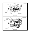
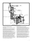
A. Piston Pump
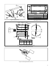
Rotation of the pump drive shaft causes the cylinder block,
shoe plate and pistons to rotate. See Figure 2. The piston
shoes are held against the yoke face by the shoe plate. The
angle of the yoke face imparts a reciprocating motion to
each piston within the cylinder block. Inlet and outlet ports
connect to a kidney slotted wafer plate. As the pistons move
out of the cylinder block, a vacuum is created and fluid is
forced into the void by atmospheric pressure. The fluid
moves with the cylinder block past the intake kidney slot to
the outlet (pressure) kidney slot. The motion of the piston
reverses and fluid is pushed out the cylinder block into the
outlet port.
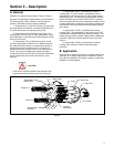
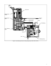
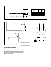
B. Compensator (Flat Cut-Off Type)
A flat cut-off compensated pump will maintain a constant
load pressure for all values of flow within the capacity of the
pump providing the load is sufficient to build up pressure.
A step by step description of the flat cut-off type compensa-
tor control follows. Refer to Figure 3 throughout this
discussion.
When a no load condition exists, the pump will deliver
maximum flow at zero pressure. As the actuator load
increases, pressure will rise; however, flow will remain at
maximum until pressure reaches the compensator spring
setting (cracking pressure). As a further increase in load
occurs, system pressure will cause the compensator spool to
move against the compensator spring, metering flow to the
yoke stroking piston. The yoke stroking piston then moves the
yoke to reduce flow. As flow is reduced, system pressure
reduces slightly causing the compensator spool to return to the
null position. At null, flow to the yoke stroking piston stops.
Movement of the yoke will stop and the flow will stabilize at a
reduce value. If the load were to continue to increase, the
pump flow will reduce to zero (0) and a deadhead pressure
condition would exist. The pressure differential needed to
cause the compensator spool to change from maximum flow
(cracking pressure) to zero flow (deadhead pressure) is
approximately 50 to 150 PSI.
Pump outlet flow is proportional to the control range from
cracking pressure to deadhead pressure. (i.e. If cracking
pressure is 2900 PSI (max. flow) and deadhead pressure is
3000 PSI (min. flow), a pressure of 2950 PSI would be equal
to 1/2 maximum flow.)
If the load decreases, pressure will decrease proportionally
and the compensator spring will move the spool down,
opening the yoke stroking piston to case drain. As fluid is
metered from the yoke stroking piston, the yoke spring will
stroke the yoke to increase flow. The increase in flow causes
a proportional increase in system pressure. The increase in
system pressure returns the compensator spool to a null
position and flow from the yoke stroking position will stop;
simultaneously, movement of the yoke will stop. The flow will
stay constant until another change of load occurs.
If the load continues to decrease, pump flow will continue too
increase, holding the outlet at compensator cracking
pressure. When maximum flow is reached (max. stroke), a
maximum flow and a maximum pressure condition exists. A
further decrease in load will lower the outlet pressure until a
final theoretical condition of maximum flow and zero
pressure is obtained.
C. Compensator (Remote Control - “CG”)
This compensator allows the operator to change the
pressure setting through the use of a remote control valve.
The “CG” compensator has the same performance
characteristics as the “C” type compensator.