


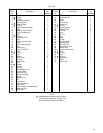
24
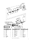
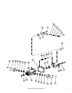
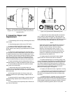
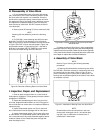
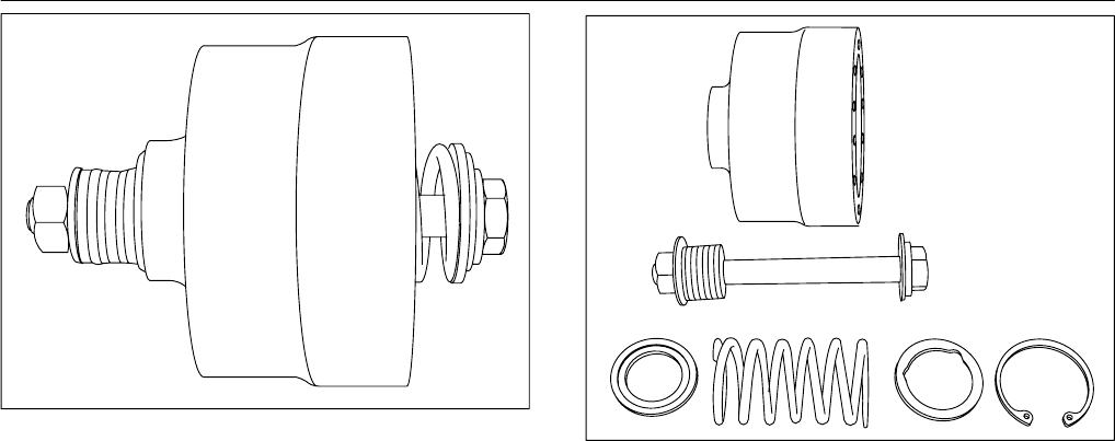
Figure 14. Cylinder block subassembly disassembly tool.
(Tighten nut, remove snap ring, loosen nut to relieve
spring tension).
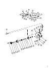
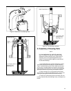
Figure 14a. Cylinder Block Subassembly parts.
F. Inspection Repair and
Replacement
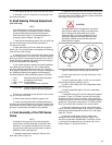
1. Check bearing (32) for scoring or brinelling of the rollers
(PVE 19/21).
2. Check bearing spacer (33) for burrs (PVE 19/21).
3. Inspect cylinder block S/A face (34) for wear,
scratches and/or erosion between cylinders. Check the
spring, washers and retaining ring located within the cylinder
block S/A.
4. Check each cylinder block bore for excessive wear.
Use the piston and shoe subassemblies (43) for this purpose.
The piston should be a very close fit and slide easily in and
out of the bore. No bind can be tolerated. If binding is evident,
clean the cylinder block and piston, lubricate with clean hy-
draulic fluid and try again. Even minor contamination of the
fluid could cause the piston to freeze up in the cylinder bore.
5. Inspect each piston and shoe subassembly (43) for a
maximum end play of 0.005 inch between the piston and shoe.
6. The face thickness dimension of each shoe must be
within 0.001 inch of each other.
7. Inspect shoe plate (42) for excessive wear and
cracking in the area of spherical washer (41). If heavy wear or
cracks are found, replace the shoe plate and spherical washer
at the same time.
8. Check spherical washer (41) for burrs, wear, and
possible scratches due to pin breakage. Replace if wear is
excessive.
9. Inspect pins (39) for equal length, excessive wear and
possible bending. Replace all pins simultaneously if one is
defective.
10. The pin retainer (40) may develop burrs. Remove all
burrs with an India stone.
11. Inspect the face of the wafer plate (28) for excessive
wear, scratches, and possible fracture. If the wafer plate is
fractured, make sure the new plate rests flat against the valve
block at assembly and that wafer plate pin (29) does not extend
too far and hold the wafer plate away from the valve block.
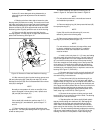
NOTE
Inspect the yoke face and shaft bearing as follows: If
either are defective, perform step F.14 and remove
the yoke from the housing. If the drive shaft is
defective, follow procedure shown in step F.17 to
remove the drive shaft from the front bearing. If the
drive shaft, shaft bearing, housing or valve block are
replaced, a shaft bearing preload adjustment must
be performed. See Section VI.K.
12. Inspect pump drive shaft (48) for wear, chipped
splines and burrs. Remove burrs with an India stone.
13. Inspect shaft bearing (61) for brinelling, pitting of the
rollers, and roughness when turned in race (62) located in the
housing. If the bearing is defective, both the bearing and the
race must be replaced. If the bearing shows no evidence of
wear, do not remove the bearing race from the housing or the
bearing from the shaft. If the bearing requires removal,
perform the following steps 14 through 18.
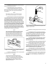
14. Inspect yoke (56) face for wear, roughness or scoring.
a. Remove the four screws (49) that hold pintle covers
(50) on each side of the housing. Remove the pintle covers.
Be careful not to damage the shims which lie directly under
the covers.
b. Retain shims (51), if possible, and use a micrometer
to measure the total shim thickness. If the bearings are not
defective, the same shims or a new shim of the same thickness
will be needed to preload the bearings at installation. Remove
O–Rings (52) and bearing spacers (53) from each pintle.