


27
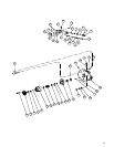
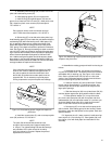
a. Assemble pintle bearings (55) on each end of the
yoke and insert bearing races (54).
b. Install bearing spacer (53) at one pintle end.
c. Install O-Ring (52) against spacer (53) into the
groove, then install a 0.010 inch shim (51) under pintle cover
(50). Install four pintle cover screws (49) and torque to
175–185 lbf. in.
NOTE
Early designs used a screw and washer arrange-
ment. These should be torqued to 115–125 lbf. in.
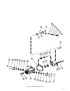
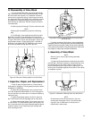
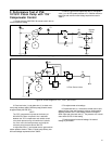
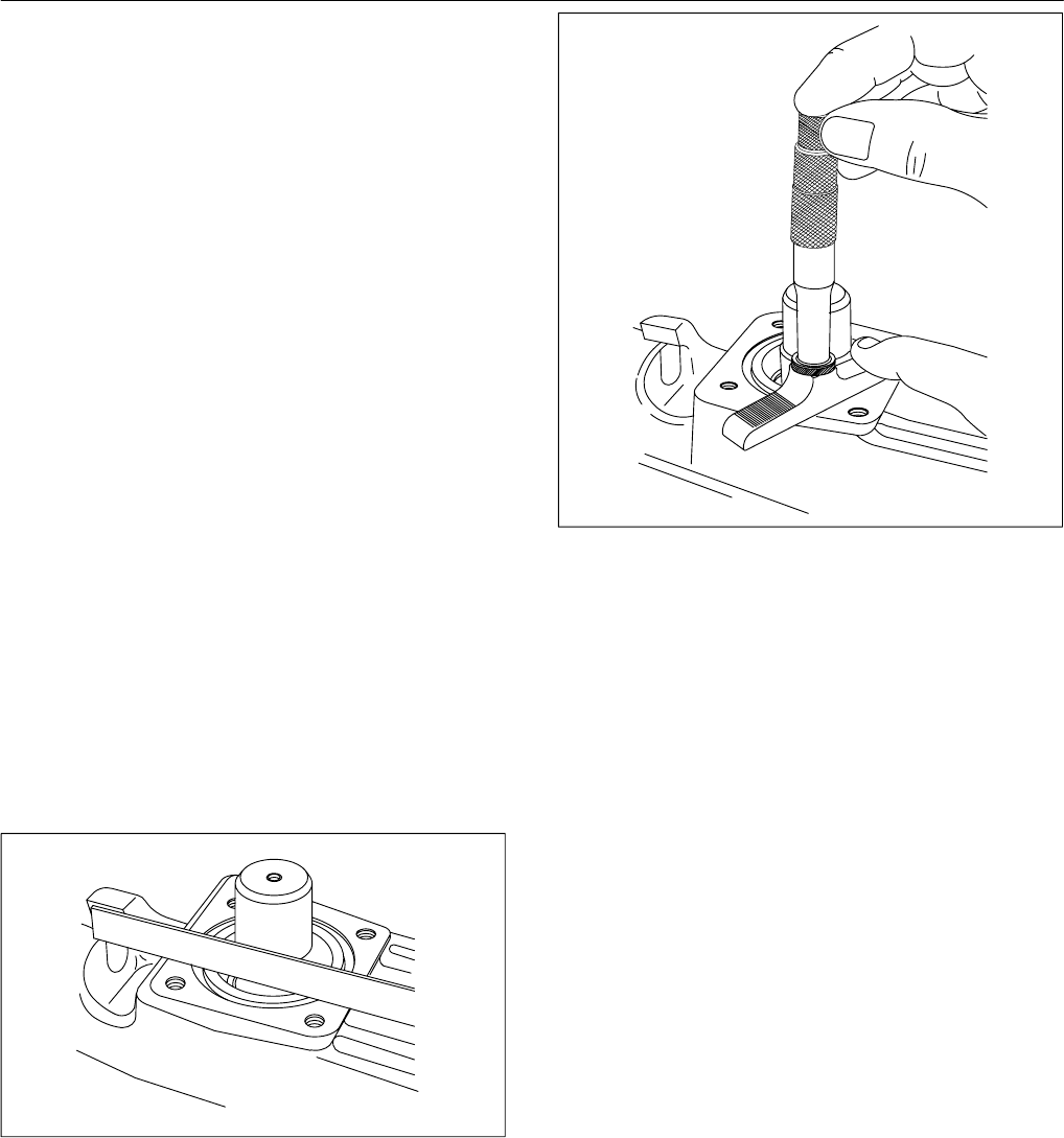
d. Set housing (27) on its side so the other pintle is up.
Install bearing spacer (53) and rotate the yoke back and forth to
seat bearings (55) within the bearing races. With spacer (53)
fully in against the bearing race, measure the height of the
spacer with respect to the housing pintle face in two places
(180° apart). Use a depth micrometer to perform this measure-
ment. See Figure 19. Average the readings to obtain a nominal
value. A 0.007-0.009 inch preload is required of the pintle bear-
ings. Calculate the necessary shims to provide this preload as
follows: Assume the depth readings were 0.029 and 0.027
inch. Add the two figures together and divide by two to obtain
the average. In this case the average calculated is 0.028 inch.
Subtract the nominal preload of 0.008 inch from the calculated
average to obtain the required shim thickness.
NOTE
If the calculated shim thickness is greater than 0.020,
another shim must be added to the opposite side of
the yoke to reduce the total shim thickness to less
than 0.020. Shim thickness at either pintle must not
exceed 0.020. This is necessary to provide proper
O-Ring compression and prevent pintle seal leakage.
Figure 19. Pintle bearing spacer height with respect to
pintle face.
e. Install the correct shims (51) and cross torque pintle
cover (50) screws to 175–185 lbf. in.
NOTE
The yoke (56) will be stiff but should be loose
enough to be moved by hand (approximately 20 lb.
in. torque). The tightness/drag indicates the bearings
are preloaded. If the yoke cannot be moved by
hand, the preload is too great. Repeat the preload
adjustment until correct.
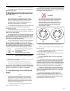
Figure 19a. Measuring height of pintle bearing spacer with
respect to the pintle face.
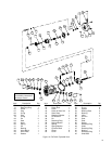
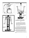
4. Assemble the rotating group and install into housing as
follows:
a. Assemble the spring, two washers and retaining
ring into the cylinder block. The washer with three notches is
assembled next to retaining ring. See Figure 14 for instruc-
tions. Set the cylinder block S/A (34) face on a flat clean
surface. Use Kraft paper between the block and surface to
prevent scratching the cylinder block face.
b. Install pin retainer (40) into cylinder block. Position
the pin retainer approximately 1/4” below the surface, and
orient the open end of the pin retainer to be away from the
large spline openings.
c. Slide the three pins (39) into cylinder block S/A (34)
until they bottom against the spring washer within the block.
d. Place spherical washer (41) on top of the three
pins, then install shoe plate (42) with nine piston and shoe
subassemblies (43) over spherical washer (41) and into cylin-
der block. Wobble shoe plate (42) to make sure that each
piston is free within its bore in the cylinder block.
e. Set housing (27) on its side and hold pump shaft
(48) horizontal. Slide rotating group into the housing. Rotate
the shaft to match the shaft splines to the cylinder block and
spherical washer.
5. If alignment pins (31) were removed, install two align-
ment rollpins (31) into housing (27). Place gasket (30) over
the rollpins, cover with Kraft paper and set aside for final
assembly.