


25
NOTE
If shims (51) were destroyed during disassembly, a
yoke bearing preload adjustment must be made at
assembly.
c. Slide the yoke from side to side to loosen the yoke
bearing races (54) within the housing. The races are a normal
slip fit but may be tight. Use an open end wrench between the
yoke and the pintle bearing to help slide out the races. Apply
pressure to bearing (55) at the approximate center and allow
the bearing rollers to gently press the race out of the housing.
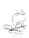
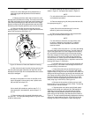
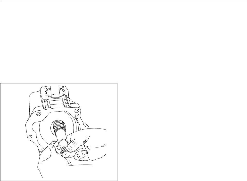
15. Remove yoke (56) and drive shaft (48) from the
housing together. Turn the yoke at an angle and slide the two
parts out of the housing. See Figure 15.
Figure 15. Removal of Yoke and Shaft from Housing.
16. After removal of yoke from the housing, remove seat
(59) and yoke spring (60). Seat (58) and rollpin (57) will be
attached to the yoke (56). Do not disassemble further unless
seat (58) is damaged.
NOTE
Normally a wear pattern will exist on seat (58). If the
seat is damaged or shows heavy wear, replace seat
(58) and (59) and rollpin (57).
NOTE
If drive shaft (48) is defective, perform step F.17. If
front bearing (61) was defective, perform steps F.17
and 18.
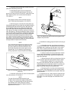
17. Remove bearing (61) from shaft (48) with the nine
inch piece of 1 1/2” heavy wall tubing shown in Figure 9. Press
off with an arbor press.
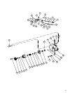
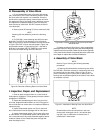
18. Remove bearing race (62) from housing (27) as
shown in Figure 16. Use special tool shown in Figure 10.
NOTE
For units without shaft seal, omit shaft seal removal
and installation procedure.
19. Remove retaining ring (44) then press shaft seal (45)
from pump housing (27).
NOTE
If yoke (56) and front shaft bearing (61) were not
defective, perform the following step.
20. Remove and replace shaft seal (42) located within
housing (27) as follows: (Refer to figure 17.)
NOTE
For units without a shaft seal, this step will be used
to remove a defective drive shaft only. In addition,
references to shaft seal installation and removal
must be omitted.
a. Install a nine inch piece of 1 1/2” heavy wall tubing
over drive shaft (48) within the housing. The end of the tub-
ing will rest against the inner race of tapered roller bearing
(61) and extend out beyond the end of the pump housing.
Place the complete unit with tubing into an arbor press with
drive spline up. Press the drive shaft through the bearing
and out of the unit. A 0.001 press exists between the shaft
and bearing so considerable force is required to remove the
bearing. See Figure 17 (PVE19/21).
b. Remove retaining ring (44) and pull shaft seal (45)
from housing (27). Be careful not to damage the aluminum
die cast housing in the seal area.
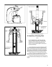
c. Press drive shaft (48) into shaft bearing (61) as
follows: Use a short piece of 1 1/2” inch heavy wall tubing
(approximately 6” long) over the drive spline of the shaft. The
tubing must be long enough to go through the shaft seal end
of the pump and make contact with the inner race of the front
bearing. Press the shaft through the bearing with an arbor
press until the bearing bottoms against the shoulder of the
shaft (snap ring on the PVE12). See Figure 18.
d. Remove the short piece of tubing and turn shaft
bearing (69) in its race with the end of the shaft. The bearing
rollers must turn free and smooth.
e. Tape the spline end of drive shaft (48) with plastic
tape to prevent cutting new shaft seal (45). Start taping the
shaft close to the housing and work toward the end of the
shaft. Install a new shaft seal in position over the shaft and
press evenly into the housing. Use shaft seal driver shown in
Figure 12. The seal must be positioned just below the retaining
ring groove. Install retaining ring (44, 47 for PVE12) into the
housing. Use internal Truarc pliers to install retaining ring.